FlexLogix Controller System User Manual 1794-L34 Firmware Revision 16 User Manual
Important User Information Solid state equipment has operational characteristics differing from those of electromechanical equipment. Safety Guidelines for the Application, Installation and Maintenance of Solid State Controls (publication SGI-1.1 available from your local Rockwell Automation sales office or online at http://literature.rockwellautomation.com) describes some important differences between solid state equipment and hard-wired electromechanical devices.
Table of Contents Summary of Changes Important User Information . . . . . . . . . . . . . . . . . . . . . . . . . . 2 Introduction . . . . . . . . . . . . . . . . . . . . . . . . . . . . . . . . . . . . . 7 Updated Information . . . . . . . . . . . . . . . . . . . . . . . . . . . . . . . 7 Preface Developing FlexLogix Controller Systems Introduction . . . . . . . . . . . . . . . . . . . . . . . . . . . . . . . . . . . . . 9 Related Documentation . . . . . . . . . . . . . . . . . . . . . . . . . . . . .
Table of Contents Chapter 5 Place, Configure, and Monitor I/O Use This Chapter . . . . . . . . . . . . . . . . . . . . . . . . . . Select I/O Modules . . . . . . . . . . . . . . . . . . . . . . . . . Place Local I/O Modules . . . . . . . . . . . . . . . . . . . . . Selecting a Power Supply . . . . . . . . . . . . . . . . . . Configure I/O . . . . . . . . . . . . . . . . . . . . . . . . . . . . . I/O connections. . . . . . . . . . . . . . . . . . . . . . . . . Configure Distributed I/O on EtherNet/IP .
Table of Contents 5 Chapter 7 Configure PhaseManager Use This Chapter . . . . . . . . . . . . . . . . . . . . . . PhaseManager Overview . . . . . . . . . . . . . . . . . State Model Overview . . . . . . . . . . . . . . . . . . . How equipment changes states . . . . . . . . . Manually change states . . . . . . . . . . . . . . . Compare PhaseManager to Other State Models. Minimum System Requirements . . . . . . . . . . . . Equipment Phase Instructions . . . . . . . . . . . . . . . . . . . . . . . . . . .
Table of Contents Publication 1794-UM001G-EN-P - January 2007
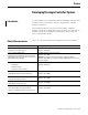
Summary of Changes Introduction This release of this document contains new and updated information. To find new and updated information, look for change bars, as shown next to this paragraph. Updated Information The document contains these changes.
Summary of Changes Notes: Publication 1794-UM001G-EN-P - January 2007
Preface Developing FlexLogix Controller Systems Introduction Use this manual to become familiar with the FlexLogix controller and its features. This version of the manual corresponds to controller firmware revision 16. This manual describes the necessary tasks to install, configure, program, and operate a FlexLogix system. In some cases, this manual includes references to additional documentation that provides the more comprehensive details.
Developing FlexLogix Controller Systems The documents address network communications: For this information: Use this publication: configure and use EtherNet/IP networks EtherNet/IP Communication Modules in Logix5000 Control Systems publication ENET-UM001 communicate over EtherNet/IP configure and use ControlNet networks communicate over ControlNet configure and use DeviceNet network communicate over DeviceNet ControlNet Communication Modules in Logix5000 Control Systems publication CNET-UM001 Devi
Chapter 1 Where to Start Use This Chapter The FlexLogix controller offers state-of-art control, communications, and I/O elements in a distributed control package..
Where to Start The FlexLogix controller, part of the Logix family of controllers, provides a small, powerful, cost-effective system built on the following components: • 1794-L34 FlexLogix controller available in 512 Kbytes of user memory. • FlexLogix controller that supports the Logix instructions. • RSLogix 5000 programming software that supports every Logix controller. • FLEX I/O modules that provide a compact, DIN-rail mounted I/O system.
Where to Start Install Hardware 13 To install a FlexLogix controller, follow these steps: Installation Step See: o 1. Install a DIN rail • o 2. Use DIN rail locks that came with your controller o 3. Mount an appropriate power supply on the DIN rail o 4. Install the battery in the controller FlexLogix Controller Installation See 8 “Maintain the Battery.“ o 5. Install the communication cards in the controller See Chapter 3 “Communicate over Networks” o 6.
Where to Start Notes: Publication 1794-UM001G-EN-P - January 2007
Chapter 2 Directly Connect to the Controller via the Serial Port Use This Chapter This chapter describes how to connect to the controller via the serial port so you can configure the controller and upload and/or download a project to the controller.
Directly Connect to the Controller via the Serial Port One possible isolator is the 1761-NET-AIC interface converter. port 2: mini-DIN 8 RS-232 baud rate selector switch port 1: DB-9 RS-232, DTE dc power source selector switch terminals for external 24V dc power supply 2. Select the appropriate cable.
Directly Connect to the Controller via the Serial Port If you are using an isolator: Use this cable: no The 1756-CP3 cable attaches the controller directly to the RS-232 device. 1 CD 1 CD 2 RDX 2 RDX 3 TXD 3 TXD 4 DTR 4 DTR COMMON COMMON 6 DSR 6 DSR 7 RTS 7 RTS 8 CTS 8 CTS 9 9 straight cable end 17 right-angle cable end If you make your own cable, it must be shielded and the shields must be tied to the metal shell (that surrounds the pins) on both ends of the cable.
Directly Connect to the Controller via the Serial Port ATTENTION The FlexLogix controller is grounded through its DIN rail. It is important that you understand the workstation’s grounding system before connecting it to the controller. An isolator is recommended between the controller and the workstation. CH Configure the Serial Driver Use RSLinx software to configure the RS-232 DF1 Device driver for serial communications. To configure the driver: 1.
Directly Connect to the Controller via the Serial Port 19 4. Specify the serial port settings: a. From the Comm Port drop-down list, select the serial port (on the workstation) that the cable is connected to. b. From the Device drop-down list, select Logix 5550-Serial Port. c. Click Auto-Configure. 5. Does the dialog box display the following message: Auto Configuration Successful! If: Then: Yes Click OK. No Go to step 4. and verify that you selected the correct Comm Port. Then click Close.
Directly Connect to the Controller via the Serial Port Select the Controller Path In RSLogix 5000 software, select the controller path on the network. 1. Open an RSLogix 5000 project for the controller. 2. From the Communications menu, select Who Active. 3. Expand the communication driver to the level of the controller. 4. Select the controller.
Chapter 3 Communicate over Networks Use This Chapter Supported networks for: The FlexLogix controller supports additional networks so that the controller can: Example: Control distributed (remote) I/O FlexLogix controller • EtherNet/IP • ControlNet • DeviceNet control network distributed (remote) I/O platform Produce/consume (interlock) data between controllers FlexLogix controller • EtherNet/IP • ControlNet control network other Logix5000 controller Send and receive messages to and from other de
Communicate over Networks This chapter summarizes the FlexLogix controller’s communications capabilities: For this information: EtherNet/IP See: • • • • • EtherNet/IP Modules in Logix5000 Control Systems User Manual, ENET-UM001 EtherNet/IP Web Server Module User Manual, ENET-UM527 EtherNet/IP Performance Application Guide, ENET-AP001 Logix5000 Controllers Design Considerations Reference Manual, 1756-RM094 EtherNet/IP Daughtercard Installation Instructions, 1788-IN054 Publication 1794-UM001G-EN-P - J
Communicate over Networks 23 The EtherNet/IP communication modules: • support messaging, produced/consumed tags, HMI, and distributed I/O • encapsulate messages within standard TCP/UDP/IP protocol • share a common application layer with ControlNet and DeviceNet • interface via RJ45, category 5, unshielded, twisted-pair cable • support half/full duplex 10 Mbps or 100 Mbps operation • support standard switches • require no network scheduling • require no routing tables In this example: • The controllers can
Communicate over Networks Connections over EtherNet/IP You indirectly determine the number of connections the controller uses by configuring the controller to communicate with other devices in the system. Connections are allocations of resources that provide more reliable communications between devices than unconnected messages. All EtherNet/IP connections are unscheduled.
Communicate over Networks ControlNet See: • • • • ControlNet Modules in Logix5000 Control Systems User Manual, CNET-UM001 Logix5000 Controllers Design Considerations Reference Manual, 1756-RM094 ControlNet Daughtercard Installation Instructions, 1788-IN002 ControlNet Daughtercard Installation Instructions, 25 For ControlNet communications, install a ControlNet communication card in your FlexLogix controller: If you are using Use this card fiber media 1788-CNF, 1788-CNFR coaxial media 1788-CNC, 1788
Communicate over Networks In this example: • The controllers can produce and consume tags among each other. • The controllers can initiate MSG instructions that send/receive data or configure devices. • The personal computer can upload/download projects to the controllers. • The personal computer can configure devices on ControlNet, and it can configure the network itself.
Communicate over Networks 27 more reliable communications between devices compared to unconnected messages. ControlNet connections can be: Connection method: Description: scheduled A scheduled connection is unique to ControlNet communications. A scheduled connection lets you send and receive data repeatedly at a predetermined interval, which is the requested packet interval (RPI).
Communicate over Networks For more information...
Communicate over Networks 29 Use these software products when you use a FlexLogix controller on DeviceNet: Software Use Required/optional RSLogix 5000 programming software Use this to configure the FlexLogix project and define DeviceNet communications. Required RSNetWorx for DeviceNet Required Use this software to configure DeviceNet devices and define the scan list for those devices.
Communicate over Networks Define Data Blocks How you configure the DeviceNet devices determines how many words you use per device. The 1788-DNBO card supports a maximum of: • 124 32-bit words of input data • 123 32-bit words of output data • 32 32-bit words of status data Most DeviceNet devices support 16-bit words. Take care how you map these into the 32-bit words used in RSLogix 5000 programming software. RSNetWorx for DeviceNet lets you DINT-align the device data.
Communicate over Networks Serial See: • Logix5000 Controllers Common Procedures Manual, 1756-PM001 31 The RS-232 port is a non-isolated serial port built-in to the front of the FlexLogix controller. You can configure the serial port of the controller for these modes: Use this mode: For: DF1 point-to-point communication between the controller and one other DF1-protocol-compatible device. This is the default system mode.
Communicate over Networks Use this mode: For: DF1 slave mode using a controller as a slave station in a master/slave serial communication network. When there are multiple slave stations on the network, link slave stations using modems or line drivers to the master. When you have a single slave station on the network, you do not need a modem to connect the slave station to the master. You can configure the control parameters for no handshaking. You can connect 2 to 255 nodes to a single link.
Communicate over Networks 33 1. Determine whether you need an isolator. For more information on determining if you need an isolator, see page 15. 2. Select the appropriate cable. 3. Connect the appropriate cable to the serial port. Communicate with DF1 devices You can configure the controller as a master or slave on a serial communication network.
Communicate over Networks To configure the controller for DF1 communications: On this tab Do this 1. Select System Mode 2. Specify communication settings 1. Select DF1 protocol 2. Specify DF1 settings For more information... The Logix5000 Controllers General Instructions Reference Manual, 1756-RM003 defines the instructions you can use to manipulate ASCII characters.
Communicate over Networks 35 Communicate with ASCII devices When configured for user mode, you can use the serial port to interface with ASCII devices. For example, you can use the serial port to: • read ASCII characters from a weigh scale module or bar code reader • send and receive messages from an ASCII triggered device, such as a MessageView terminal.
Communicate over Networks To configure the controller for ASCII communications: On this tab Do this 1. Select User Mode 2. Specify communication settings 1. Select ASCII protocol 2.
Communicate over Networks 37 The controller supports several instructions to manipulate ASCII characters. The instructions are available in ladder diagram (LD) and structured text (ST).
Communicate over Networks Convert data to or from ASCII characters If you want to: For more information...
Communicate over Networks DH-485 39 For DH-485 communication, use the serial port of the controller. However, when using a FlexLogix controller, it is recommended that you use NetLinx networks (EtherNet/IP, ControlNet, or DeviceNet) because excessive traffic on a DH-485 network may make it impractical to connect to a controller with RSLogix 5000 programming software.
Communicate over Networks On the DH-485 network, the FlexLogix controller can send and receive messages to and from other controllers on the network. IMPORTANT A DH-485 network consists of multiple cable segments. Limit the total length of all the segments to 1219m (4000 ft.). For the controller to operate on a DH-485 network, you need: • a 1761-NET-AIC interface converter for each controller you want to put on the DH-485 network.
Communicate over Networks 41 • RSLogix 5000 programming software to configure the serial port of the controller for DH-485 communications. Specify these characteristics on the Serial Port tab (default values are shown in bold): Characteristic: Description: Baud Rate Specifies the communication rate for the DH-485 port. All devices on the same DH-485 network must be configured for the same baud rate. Select 9600 or 19200 Kbps.
Communicate over Networks Third Party The FlexLogix controller can operate on third-party networks. To operate on a third-party network, install the 1788-MODULE generic module communication card in the controller.
Communicate over Networks 43 Size The size field determines how large the connections are between the owner-controller and the I/O module. Connections are sent in sizes matching the communications format data type selected. The default, DINT, results in 32-bit quantities. Complete your system configuration and develop your program logic. Then download the project to the controller.
Communicate over Networks Notes: Publication 1794-UM001G-EN-P - January 2007
Chapter 4 Manage Controller Communications Use This Chapter For this information Produce and Consume (Interlock) Data See Produce and Consume (Interlock) Data 45 Send and Receive Messages 47 Connection Overview 49 Calculate Connection Use 50 Connections Example 52 The controller supports the ability to produce (broadcast) and consume (receive) system-shared tags over ControlNet or EtherNet/IP networks. Produced and consumed tags each require connections.
Manage Controller Communications This type of tag Description produced A produced tag allows other controllers to consume the tag, which means that a controller can receive the tag data from another controller. The producing controller uses one connection for the produced tag and one connection for each consumer. The controller’s communication device uses one connection for each consumer.
Manage Controller Communications Send and Receive Messages 47 Messages transfer data to other devices, such as other controllers or operator interfaces. Messages use unscheduled connections to send or receive data. Connected messages can leave the connection open (cache) or close the connection when the message is done transmitting.
Manage Controller Communications The controller has the following limits on the number of connections that you can cache: If you have this software and firmware revision: 11.x or earlier Then you can cache: • block transfer messages for up to 16 connections • other types of messages up to 16 connections 12.x or later For more information... up to 32 total connections The Logix5000 Controllers General Instructions Reference Manual, 1756-RM003 describes how to use the MSG instruction.
Manage Controller Communications Connection Overview See: • Logix5000 Controllers Design Considerations Reference Manual, 1756-RM094 49 A Logix5000 system uses a connection to establish a communication link between two devices.
Manage Controller Communications Calculate Connection Use To calculate the total number of local connections the controller uses: Connection Type: Device Quantity: Connections per Device: Total Connections: rack-optimized connection for the local DIN rail and the extended-local DIN rail 2 1 2 I/O module (rack-optimized connection) on local rail 0 I/O module (direct connection) on local rail 1 I/O module (rack-optimized connection) on extended-local rail 0 I/O module (direct connection)
Manage Controller Communications Remote Connection Type Device Quantity Connections per Device message (depending on type) 1 block-transfer message 1 51 Total Connections total Publication 1794-UM001G-EN-P - January 2007
Manage Controller Communications Connections Example In this example system the FlexLogix controller: • controls local (in the same chassis) digital I/O modules • controls remote I/O devices on DeviceNet • sends and receives messages to/from a ControlLogix controller on EtherNet/IP • produces one tag that the the CompactLogix controller consumes • is programmed via RSLogix 5000 programming software 1769-ADN adapter with Compact I/O modules Redistation Series 9000 photoeye DeviceNet network ControlLog
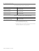
Chapter 5 Place, Configure, and Monitor I/O Use This Chapter For this information: Select I/O Modules See: • FLEX I/O and FLEX EX Selection Guide, 1794-SG002 See: Select I/O Modules 53 Place Local I/O Modules 54 Configure I/O 55 Configure Distributed I/O on EtherNet/IP 59 Configure Distributed I/O on ControlNet 60 Configure Distributed I/O on DeviceNet 61 Address I/O Data 62 Determine When Data Is Updated 63 Reconfigure an I/O Module 66 When selecting 1794 FLEX I/O modules, select:
Place, Configure, and Monitor I/O Place Local I/O Modules The FlexLogix controller supports a local DIN rail of as many as 8 I/O modules and an extended-local DIN rail of as many as 8 I/O modules. The second DIN rail is optional. See: • • FLEX I/O Analog Modules User Manual, 1794-6.5.2 FLEX I/O Digital Modules User local DIN rail extended-local DIN rail Selecting a Power Supply In a FlexLogix system, select an Allen-Bradley power supply.
Place, Configure, and Monitor I/O 55 The FlexLogix controller also supports distributed (remote) I/O via these networks: • EtherNet/IP • ControlNet • DeviceNet Configure I/O To communicate with an I/O module in your system, you add the module to the I/O Configuration folder of the controller.
Place, Configure, and Monitor I/O When you add a module, you also define a specific configuration for the module. While the configuration options vary from module to module, there are some common options that you typically configure: Configuration Option: Description: requested packet interval (RPI) The RPI specifies the period at which data updates over a connection. For example, an input module sends data to a controller at the RPI that you assign to the module.
Place, Configure, and Monitor I/O 57 I/O connections A Logix5000 system uses connections to transmit I/O data. A connection can be: Connection: Description: direct A direct connection is a real-time, data transfer link between the controller and an I/O module. The controller maintains and monitors the connection between the controller and the I/O module.
Place, Configure, and Monitor I/O Connections for remote devices To optimize the number of available connections, place remote, digital I/O in the same location and use a rack-optimized connection to the remote adapter that connects the remote I/O to the FlexLogix system. If you have remote analog I/O modules, or want a direct connection to specific remote I/O modules, you do not have to create the rack-optimized connection to the remote adapter.
Place, Configure, and Monitor I/O Configure Distributed I/O on EtherNet/IP 59 To communicate with distributed I/O modules over EtherNet/IP, you: • install a 1788-ENBT communication card in your FlexLogix controller and add the card to the I/O configuration folder • add an EtherNet/IP adapter, and I/O modules to the I/O Configuration folder of the controller. Within the I/O Configuration folder, you organize the modules into a hierarchy (tree/branch, parent/child).
Place, Configure, and Monitor I/O Configure Distributed I/O on ControlNet To communicate with distributed I/O modules over ControlNet, you: • install a 1788-CNx communication card in your FlexLogix controller and add the card to the I/O configuration folder • add a ControlNet adapter, and I/O modules to the I/O Configuration folder of the controller. Within the I/O Configuration folder, you organize the modules into a hierarchy (tree/branch, parent/child).
Place, Configure, and Monitor I/O Configure Distributed I/O on DeviceNet 61 To communicate with the I/O modules over Device, you add the DeviceNet bridge to the I/O Configuration folder of the controller. You define a scanlist within the DeviceNet adapter to communicate data between devices and the controller.
Place, Configure, and Monitor I/O Address I/O Data I/O information is presented as a set of tags. • Each tag uses a structure of data. The structure depends on the specific features of the I/O module. • The name of the tags is based on the location of the I/O module in the system. An I/O address follows this format: Location :Slot :Type .Member .SubMember .
Place, Configure, and Monitor I/O Determine When Data Is Updated 63 FlexLogix controllers update date asynchronous with the execution of logic. Use the following flowchart to determine when a producer (controller, input module, or bridge module) will send data. output input or output data? digital analog or digital? input analog digital analog or digital? remote or local? analog COS for any point on the module? No RTS ≤ RPI? No remote Yes local Yes Data is sent to the backplane at the RTS.
Place, Configure, and Monitor I/O Monitor I/O Modules The FlexLogix controller offers different levels at which you can monitor I/O modules.
Place, Configure, and Monitor I/O 65 Monitor a rack-optimized connection The controller views the DIN rail as another module in the system. Each DIN rail has its own data. To view this data through the programming software: 1. In the Controller Organizer, select Controller Tags. Right-click to display the Data Monitor. 2. Expand the data display as necessary.
Place, Configure, and Monitor I/O Reconfigure an I/O Module If an I/O module support reconfiguration, you can reconfigure the module via: • Module Properties dialog in RSLogix 5000 software • MSG instruction in program logic WARNING Use care when changing the configuration of an I/O module. You could inadvertently cause the I/O module to operate incorrectly.
Place, Configure, and Monitor I/O 67 Reconfigure a module via a MSG instruction To change the configuration of an I/O module programmatically, use a MSG instruction of type Module Reconfigure to send new configuration information to an I/O module. During the reconfiguration: • Input modules continue to send input data to the controller. • Output modules continue to controller their output devices.
Place, Configure, and Monitor I/O Notes: Publication 1794-UM001G-EN-P - January 2007
Chapter 6 Develop Applications Use This Chapter For this information: Manage Tasks See: • • Logix5000 Controllers Common Procedures Manual, 1756-PM001 Logix5000 Controllers Design Considerations Reference Manual, See: Manage Tasks 69 Develop Programs 70 Organize Tags 75 Select a Programming Language 76 Monitor Controller Status 79 Monitor Connections 80 Select a System Overhead Percentage 82 Use the Event Task 85 A Logix5000 controller lets you use multiple tasks to schedule and prior
Develop Applications Develop Programs The controller operating system is a preemptive multitasking system that is IEC 1131-3 compliant.
Develop Applications 71 Defining tasks A task provides scheduling and priority information for a set of one or more programs. You can configure tasks as continuous, periodic, or event. Only one task can be continuous. A task can have as many as 100 separate programs, each with its own executable routines and program-scoped tags. Once a task is triggered (activated), all the programs assigned to the task execute in the order in which they are grouped.
Develop Applications However, if you schedule two high priority tasks (1 to 5) to run every millisecond, and they both require 500 μs or more to execute, no CPU time would be left for the dedicated I/O task. Furthermore, if you have so much configured I/O that the execution time of the dedicated I/O task approaches 2 ms (or the combination of the high priority tasks and the dedicated I/O task approaches 2 ms) no CPU time is left for low priority tasks (7 to 15).
Develop Applications 73 Notes: A. The highest priority task interrupts all lower priority tasks. B. The dedicated I/O task can be interrupted by tasks with priority levels 1 to 7. The dedicated I/O task interrupts tasks with priority levels 7 to 15. This task runs at the selected RPI rate scheduled for the FlexLogix system (5 ms in this example). C. The continuous task runs at the lowest priority and is interrupted by all other tasks. D.
Develop Applications Sample controller projects RSLogix 5000 Enterprise programming software includes sample projects that you can copy and then modify to fit your application. From RSlogix 5000 software, select Help → Vendor Sample Projects to display a list of available, sample projects. Scroll down to here and select the appropriate set of sample projects For more information...
Develop Applications Organize Tags With a Logix5000 controller, you use a tag (alphanumeric name) to address data (variables). In Logix5000 controllers, there is no fixed, numeric format. The tag name itself identifies the data.
Develop Applications Select a Programming Language The FlexLogix controller supports these programming languages, both online and offline: If you are programming: Use this language: continuous or parallel execution of multiple operations (not sequenced) ladder diagram (LD) boolean or bit-based operations complex logical operations message and communication processing machine interlocking operations that service or maintenance personnel may have to interpret in order to troubleshoot the machine or
Develop Applications 77 Add-On Instructions With version 16 of RSLogix 5000 programming software, you can design and configure sets of commonly used instructions to increase project consistency. Similar to the built-in instructions contained in Logix5000 controllers, these instructions you create are called Add-On Instructions. Add-On Instructions reuse common control algorithms. With them, you can: • ease maintenance by animating logic for a single instance.
Develop Applications unique name so that you don’t accidentally overwrite another instruction of the same name. Use Context Views Context views let you visualize an instruction’s logic for a specific instant, simplifying online troubleshooting of your Add-On Instructions. Each instruction contains a revision, a change history, and an auto-generated help page.
Develop Applications Monitor Controller Status 79 The FlexLogix controller uses Get System Value (GSV) and Set System Value (SSV) instructions to get and set (change) controller data. The controller stores system data in objects. There is no status file, as in the PLC-5 processor. The GSV instruction retrieves the specified information and places it in the destination. The SSV instruction sets the specified attribute with data from the source.
Develop Applications Monitor Connections See: • • Logix5000 Controllers Common Procedures Manual, 1756-PM001 Logix5000 Controllers Design Considerations Reference Manual, If communication with a device in the I/O configuration of the controller does not occur for 100 ms or 4 times the RPI (whichever is less), the communication times out and the controller produces the following warnings: • The I/O LED on the front of the controller flashes green.
Develop Applications 81 • If Module_Status is any value other than 4, the controller is not communicating with the module. Interrupt the execution of logic and execute the fault handler 1. In the controller organizer, right-click the module and select Properties. 2. Click the Connection tab. 3. Select (check) the Major Fault If Connection Fails While in Run Mode check box.
Develop Applications 4. Develop a routine for the Controller Fault Handler. See the Logix5000 Controllers Common Procedures, publication 1756-PM001. Select a System Overhead Percentage 1. The Controller Properties dialog lets you specify a percentage for system overhead. This percentage specifies the percentage of controller time (excluding the time for periodic tasks) that is devoted to communication and background functions. View properties for the controller and select the Advanced tab.
Develop Applications 83 the system overhead percentage does increase communications performance, it also increases the amount of time it takes to execute a continuous task - increasing overall scan time The table below shows the ratio between the continuous task and the system overhead functions: At this time slice: The continuous tasks runs for: And then overhead occurs for up to: 10% 9 ms 1 ms 20% 4 ms 1 ms 33% 2 ms 1 ms 50% 1 ms 1 ms At a time slice of 10%, system overhead interrupts the
Develop Applications If you use the default time slice of 20%, the system overhead interrupts the continuous task every 4 ms (of continuous task time). 1 ms 1 ms 1 ms 1 ms 1 ms system overhead 4 ms 4 ms 4 ms 4 ms 4 ms continuous task 5 10 15 20 25 elapsed time (ms) If you increase the time slice to 50%, the system overhead interrupts the continuous task every 1 ms (of continuous task time).
Develop Applications Use the Event Task 85 The event task is available with FlexLogix controllers using firmware version 12.x or greater. Previously, the only tasks available were the continuous task and periodic task. However, the event task offers FlexLogix controller users a task that executes a section of logic immediately when an event occurs. An event task performs a function only when a specific event (trigger) occurs.
Develop Applications Triggering the Event Task To trigger an event task based on conditions in your logic, use the EVENT Instruction trigger. Let an event trigger this task. Let an EVENT instruction trigger the task. No tag is required. The EVENT Instruction Only trigger requires that you use a Trigger Event Task (EVENT) instruction to trigger the task. You can use an EVENT instruction from multiple points in your project. Each time the instruction executes, it triggers the specified event task.
Develop Applications 87 Programmatically Determine if an EVENT Instruction Triggered a Task To determine if an EVENT instruction triggered an event task, use a Get System Value (GSV) instruction to monitor the Status attribute of the task. Status Attribute of the TASK Object Attribute: Data Type: Instruction: Description: Status DINT GSV Provides status information about the task. Once the controller sets a bit, you must manually clear the bit to determine if another fault of that type occurred.
Develop Applications Notes: Publication 1794-UM001G-EN-P - January 2007
Chapter 7 Configure PhaseManager Use This Chapter For this information: See: • The PhaseManager option of RSLogix 5000 software gives you a state model for your equipment. This chapter summarizes: PhaseManager User Manual, LOGIX-UM001 PhaseManager Overview See: PhaseManager Overview 89 State Model Overview 91 Compare PhaseManager to Other State Models 94 Minimum System Requirements 94 Equipment Phase Instructions 95 PhaseManager lets you add equipment phases to your controller.
Configure PhaseManager Here’s how the PhaseManager into RSLogix 5000 programming software: A PHASE tag gives you the status of an equipment phase. Controller Controller Tags Tasks MainTask An equipment phase directs 1 activity of your equipment. A state model divides the activity into a series of states. Add Water Phase Mix Phase Running State Routine How to add water Drain Phase Space Parts Phase MainProgram Equipment phase instructions control the transitions between states, handle faults, etc.
Configure PhaseManager State Model Overview 91 A state model divides the operating cycle of your equipment into a series of states. Each state is an instant in the operation of the equipment. It's the actions or conditions of the equipment at a given time. In a state model, you define what your equipment does under different conditions, such as run, hold, stop, etc. You don’t need to use all the states for your equipment. Use only the states that you want.
Configure PhaseManager With a state model, you define the behavior of your equipment and put it into a brief functional specification. In this way you show what happens and when it happens.
Configure PhaseManager 93 PhaseManager uses the following transitions: = transition Command Done — No command. Use PSC instruction instead. Start Idle Hold Running Holding Held Your equipment can go from any state in the box to the stopping or aborting state.
Configure PhaseManager Manually change states RSLogix 5000 software has a window that lets you monitor and command an equipment phase. State that the equipment phase is in right now To manually change states: 1. Take ownership of the equipment phase. 2. Give a command.
Configure PhaseManager Equipment Phase Instructions 95 The controller supports several instructions to support equipment phases. The instructions are available in ladder diagram (LD) and structured text (ST).
Configure PhaseManager Notes: Publication 1794-UM001G-EN-P - January 2007
Chapter 8 Maintain the Battery Using this Appendix Storing Replacement Batteries For information about: See page Storing Replacement Batteries 97 Estimating Battery Life 98 Replacing a Battery 99 Because a battery may leak potentially dangerous chemicals if stored improperly, store batteries as follows: ATTENTION 97 Store batteries in a cool, dry environment. We recommend 25° C with 40% to 60% relative humidity.
Maintain the Battery Estimating Battery Life When the battery is about 95 percent discharged, the controller provides the following warnings: • On the front of the controller, the BATTERY LED turns on (solid red). • A minor fault occurs (type 10, code 10).
Maintain the Battery 99 Use the off-time percentage you calculated with the following table to determine battery life: Worst-case battery life estimate: Catalog number: Temperature: Power off 100%: Power off 50%: Battery duration after the LED turns on:(1) 1794-L34 60° C 1.8 years 3.6 years 3 days 25° C 6.7 months 1.1 year 3 days (1) The battery indicators (BATTERY) warns you when the battery is low.
Maintain the Battery 3. Remove the old battery. 4. Install a new 1756-BA1 battery. ATTENTION Only install a 1756-BA1 battery. If you install a different battery, you may damage the controller. 5. Attach the battery label: a. Write on the battery label the date you install the battery. b. Attach the label to the inside of the battery compartment. 6. On the front of the controller, is the BATTERY LED off? If: Then: Yes Go to the next step. No A.
Appendix A FlexLogix System Status Indicators Controller LEDs The table below describes the controller LEDs present on all FlexLogix controllers. If this indicator: is in this condition: It means: RUN off The controller is in Program or Test mode. steady green The controller is in Run mode. off No tags contain I/O force values. I/O forces are inactive (disabled). steady amber I/O forces are active (enabled). I/O force values may or may not exist.
FlexLogix System Status Indicators Notes: Publication 1794-UM001G-EN-P - January 2007
Appendix B FlexLogix Back-Up on DeviceNet Using This Appendix For information about: See page How the Back-up Works 104 Power-Up and System Start-up 106 Developing the FlexLogix Back-Up Application 108 Using Indicators to Check Status 115 Development and Debugging Tips 115 This chapter offers a solution to back-up your FlexLogix controller on DeviceNet.
FlexLogix Back-Up on DeviceNet How the Back-up Works Figure shows an example back-up system. In the back-up system, the following occurs: • Both controllers/scanners simultaneously receive all inputs. • Both controllers execute in parallel but are NOT synchronized. • Only the primary controllers sends output data to the I/O devices. A virtual switch in the 1788-DNBO cards is used to switch outputs between primary and secondary controllers.
FlexLogix Back-Up on DeviceNet 105 Requirements of the Back-Up The FlexLogix Back-Up on DeviceNet solution requires that you use the following: • RSLogix 5000, version 10 or higher • 2 FlexLogix controllers, firmware revision 10.x or higher • 2 1788-DNBO communication cards, firmware revision 2.x or higher IMPORTANT Many applications use multiple communications cards in a FlexLogix controller to communicate with several networks.
FlexLogix Back-Up on DeviceNet Power-Up and System Start-up To configure a FlexLogix Back-up system on DeviceNet, you can take the following steps. Some of these steps are described in greater detail in the rest of the appendix. 1. Install all I/O and operator interfaces that you need to back-up on DeviceNet. We recommend that you reserve node addresses 0 and 1 for the two FlexLogix controllers used in the back-up.
FlexLogix Back-Up on DeviceNet 107 9. Connect the other FlexLogix controller with a 1788-DNBO scanner on the network. 10. Set the node address to 0. 11. Power-up the controller and scanner. 12. Use RSNetWorx for DeviceNet to download the same scanlist used in step 5. It may be necessary to browse the network again before downloading the scanlist. This second browsing of the network allows RSNetWorx for DeviceNet to establish communication to the new scanner at the same node number as the previous scanner.
FlexLogix Back-Up on DeviceNet Developing the FlexLogix Back-Up Application The FlexLogix back-up is enabled from an RSLogix 5000 user program with a few simple ladder rungs (or equivalent).
FlexLogix Back-Up on DeviceNet 109 Setting the Heartbeat Constant You can set the heartbeat constant with five rungs of ladder logic. Figure shows rungs 0 & 1 and the message set-up used in rung 1. The message in rung 1 uses the INT data type.
FlexLogix Back-Up on DeviceNet Figure shows rung 2 and the message set-up used on it. The message in rung 2 uses the INT data type.
FlexLogix Back-Up on DeviceNet 111 Figure shows rungs 3 & 4 and the message set-up used on it. The message in rung 3 uses the INT data type. Rung 3 message configuration and communication tabs This completes the required portion of ladder logic to enable the FlexLogix back-up on DeviceNet. The following sections describe how to use additional ladder logic to read back-up state and status. However, these sections are not required to complete the back-up solution.
FlexLogix Back-Up on DeviceNet Reading Back-up State Rung You can read the back-up state of the DeviceNet scanner with a single rung of ladder logic. The back-up state is useful for debug or more sophisticated back-up schemes. The message in this rung uses the SINT data type. Figure shows the rung you can use to read the back-up state.
FlexLogix Back-Up on DeviceNet 113 Table describes the possible values this message may return when reading the back-up state of the DeviceNet scanner. If the message reads this value: the back-up state of the DeviceNet scanner is: 0 Disabled 1 Primary scanner 2 Back-up scanner 3 Invalid primary node address (e.g. the node address cannot be 62 or 63) 4 Faulted back-up scanner - CRC failure (e.g.
FlexLogix Back-Up on DeviceNet Reading Back-up Status You can read the back-up status of the DeviceNet scanner with a single rung of ladder logic. The back-up state is useful for debugging or more sophisticated back-up schemes. The message in this rung uses the SINT data type. Figure shows the rung you can use to read the back-up state.
FlexLogix Back-Up on DeviceNet Using Indicators to Check Status The 1788-DNBO card’s status indicators provide useful information (e.g. determining which controller is primary) about back-up scanner status. Table lists the indicators to monitor when checking back-up status.
FlexLogix Back-Up on DeviceNet • The I/O during switchover is NOT bumpless. Since the programs and I/O updates are not synchronized, it is possible for the secondary controller to be either slightly faster or slower than the primary. For example, if output changes during a switchover, the fact that the primary and secondary controllers are unsynchronized can cause the output to momentarily switch between an older and newer value.
Appendix C Instruction Locator Where to Find an Instruction This locator table lists the available instructions, which publications describe the instructions, and which programming languages are available for the instructions.
Instruction Locator Instruction: Location: Languages: Instruction: Location: Languages: BRK Break general relay ladder DFF D Flip-Flop process control structured text function block BSL Bit Shift Left general relay ladder DIV Divide general BSR Bit Shift Right general relay ladder relay ladder structured text function block general BTD Bit Field Distribute general DTOS DINT to String relay ladder structured text general relay ladder BTDT Bit Field Distribute with Target ge
Instruction Locator Instruction: Location: Languages: Instruction: Location: Languages: INSERT Insert String general relay ladder structured text MAHD Motion Apply Hookup Diagnostics motion relay ladder structured text INTG Integrator process control structured text function block MAJ Motion Axis Jog motion relay ladder structured text IOT Immediate Output general MAM Motion Axis Move motion relay ladder structured text IREF Input Reference general MAOC Motion Arm Output Cam motion
Instruction Locator Instruction: Location: Languages: Instruction: Location: Languages: MDF Motion Direct Drive Off motion relay ladder structured text MVMT Masked Move with Target general structured text function block MDO Motion Direct Drive On motion relay ladder structured text NEG Negate general MDOC Motion Disarm Output Cam motion relay ladder structured text relay ladder structured text function block general MDR Motion Disarm Registration motion relay ladder structured
Instruction Locator Instruction: Location: Languages: Instruction: Location: Languages: PIDE Enhanced PID process control structured text function block SIN Sine general PMUL Pulse Multiplier process control structured text function block relay ladder structured text function block general PPD Equipment Phase Paused phase SIZE Size In Elements relay ladder structured text process control POSP Position Proportional process control SNEG Selected Negate structured text function block p
Instruction Locator Instruction: Location: Languages: TONR Timer On Delay with Reset general structured text function block TOT Totalizer process control structured text function block TRN Truncate general relay ladder function block TRUNC Truncate general structured text UID User Interrupt Disable general relay ladder structured text UIE User Interrupt Enable general relay ladder structured text UPDN Up/Down Accumulator process control structured text function block UPPER Uppe
Index A add-on instructions 77 address data 62 AOI 77 architecture 11 ASCII characters 37-38 B back-up FlexLogix back-up on DeviceNet 103-116 battery catalog number 97 how to replace 99 life 98 storage 97 when to replace 98 BOOTP 22 C cables DH-485 link cable length 40 cache message 47 calculate connection use 50 change of state 56 command give 92 communication ControlNet 25-28 determine timeout with any device 80 determine timeout with I/O module 80 DeviceNet 28-30 DH-485 39, 39-41 EtherNet/IP 22-24 form
Index D design 12 develop application define tasks 71-73 fault handler 81 for more information 74 monitor connection 80-82 monitor status 79 overview 69 programming language 76 programs 70 sample controller projects 74 tag 75 task 69 using event task 85-87 DeviceNet distributed I/O 61 example configuration 29 FlexLogix back-up on the network 103-116 for more information 30 module capability 29 overview 28-30 software use 29 DF1 device 33 DH-485 cables 40 controller communication 39-41 controller confi
Index instruction locator 117 isolator connected to the serial port 15-17 L ladder diagram 76 language 76 locator 117 Logix5000 controller environment 11 low battery 98 M message cache 47 connection use 47-48 for more information 48 overview 21 reconfigure I/O module 67 Modbus support 38 monitor rack-optimized connection 65 N network overview 21 P phase See equipment phase priority 71 produce data connection use 45 for more information 46 overview 21 program defining 73 programming language 76 project
Index T tag consumed 46 for more information 75 organize 75 produced 46 task 69 defining 71 priority 71 troubleshooting 101 Publication 1794-UM001G-EN-P - January 2007 U unscheduled 27 update 63 W where to start 11
How Are We Doing? Your comments on our technical publications will help us serve you better in the future. Thank you for taking the time to provide us feedback. You can complete this form and mail (or fax) it back to us or email us at RADocumentComments@ra.rockwell.com Pub. Title/Type FlexLogix Controller System User Manual Cat. No. 1794-L34 Pub. No. 1794-UM001G-EN-P Pub. Date January 2007 Part No. 953014-91 Please complete the sections below.
PLEASE FASTEN HERE (DO NOT STAPLE) PLEASE FOLD HERE NO POSTAGE NECESSARY IF MAILED IN THE UNITED STATES BUSINESS REPLY MAIL FIRST-CLASS MAIL PERMIT NO.
Rockwell Automation Support Rockwell Automation provides technical information on the Web to assist you in using its products. At http://support.rockwellautomation.com, you can find technical manuals, a knowledge base of FAQs, technical and application notes, sample code and links to software service packs, and a MySupport feature that you can customize to make the best use of these tools.