
User guide

3
Publication 1794-IN095A-EN-P - April 2004
Wiring Connections for the 1794-IV16, 1794-OV16 and
1794-OV16P
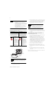
1794-TB2, -TB3 and -TB3S Terminal Base Wiring for 1794-IV16,
1794-OV16 and 1794-OV16P
2 and 3-Wire Input Wiring for 1794-IV16
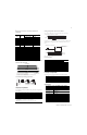
Configuring Your Input Module
You configure your input module by setting bits in the configuration
word (word 3).
Setting the Input Filter Time for the 1794-IV16
To set the input filter time, set the associated bits in the output image
(complementary word) for the module.
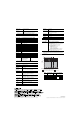
For example, to set a filter time of 8ms for a dc input module at address rack 1,
module group 0, in configuration word 3, set bits 08, 09 and 10 as shown
below.
Refer to the table for additional filter times available.
Input Filter Times
Configuring Your Output Module
You configure your output module by setting bits in word 1.
Specifications
Channel Signal
Power Terminal
Common Terminal
1
1794-OV16, 1794-OV16P,
1794-IV16
1
1794-IV16
0 A-0 C-35 B-17
1 A-1 C-36 B-18
2 A-2 C-37 B-19
3 A-3 C-38 B-20
4 A-4 C-39 B-21
5 A-5 C-40 B-22
6 A-6 C-41 B-23
7 A-7 C-42 B-24
8 A-8 C-43 B-25
9 A-9 C-44 B-26
10 A-10 C-45 B-27
11 A-11 C-46 B-28
12 A-12 C-47 B-29
13 A-13 C-48 B-30
14 A-14 C-49 B-31
15 A-15 C-50 B-32
+V dc C-34 thru C-51 are internally connected together
Common B-16 thru B-33 are internally connected together
1
2-wire sourcing input devices use the input and common terminals.
3-wire sourcing input devices use the input, common and power terminals.
Dec. 15 14 13 12 11 10 9 8 7 6 5 4 3 2 1 0
Oct. 17 16 15 14 13 12 11 10 7 6 5 4 3 2 1 0
Read 0 I15 I14 I13 I12 I11 I10 I9 I8 I7 I6 I5 I4 I3 I2 I1 I0
Read 1 C = Counter Input value of input 15
Write Not used CR CF NU Input Filter FT 0-15 Not used
WhereI = Input
C = Counter value for input 15
FT = Input filter tim
CR = Counter Reset
CF = Counter Fast - where 1 = Fast input (raw) data; 0 = Standard input filtered data
NU = Not used
Note: C, CR and CF not available when used with any series 1794-ASB or -ASB2 Remote I/O Adapters.
17 18 19 20 21 22 23 24 25 26 27 28 29 30 31 32 33
0 1 2 3 4 5 6 7 8 9 10 11 12 13 14 15
16
35 36 37 38 39 40 41 42 43 44 45 46 47 48 49 50 51
34
Inputs/Outputs
Commons
(1794-TB3 show
n)
Connect V dc common to terminal B-16
Connect +V dc power to terminal C-34
-V
Voltage
In +V
Voltage
Out +V
Voltage
A
B
C
(Use B-33 and C-51 for daisy-chaining to next terminal base unit)
Common
-V
Common
= 24V dc
= Common
= Source Input
0 -15
34-51
16-33
A
B
C
p/
2-Wire Device
(Sinking Output)
A
B
C
01 0 1
3-Wire Device
(Sinking Output)
0
16
34
Bits Description
Selected
Filter Time
10 09 08 Filter Time for inputs 00-15 (00-17)
0 0 0 Filter Time 0 (Default) 0.25ms
0 0 1 Filter Time 1 0.50ms
0 1 0 Filter Time 2 1ms
0 1 1 Filter Time 3 2ms
1 0 0 Filter Time 4 4ms
1 0 1 Filter Time 5 8ms
1 1 0 Filter Time 6 16ms
1 1 1 Filter Time 7 32ms
Dec. 15 14 13 12 11 10 9 8 7 6 5 4 3 2 1 0
Oct. 17 16 15 14 13 12 11 10 7 6 5 4 3 2 1 0
Read 0 Not used
Write 1 IO
15
O
14
O
13
O
12
O
11
O
10
O
9
O
8
O
7
O
6
O
5
O
4
O
3
O
2
O
1
O
0
Where O = Output
Specifications - 16 Source Input Module, Cat. No. 1794-IV16
Number of Inputs 16, nonisolated, sourcing
Module Location Cat. No. 1794-TB3, -TB3S
On-state Voltage 10V dc minimum
24V dc nominal
31.2V dc maximum
On-state Current 2.0mA minimum
8.0mA nominal at 24V dc
11.0mA maximum
Off-state Voltage 5.0V dc maximum
Off-state Current 1.5mA minimum
Input Impedance 4.7K ohms maximum
Isolation Voltage Tested at 2121V dc for 1s between user and system
No isolation between individual channels
Flexbus Current 30mA
Power Dissipation 5.7W maximum @ 31.2V dc
Thermal Dissipation Maximum 19.4 BTU/hr @ 31.2V dc
O:010
09 08 07 06 05 04 03 02 01
00
15 14 13 12 11 10
Dec.
FT = 00 thru 15
0
Fill File
Source
Destination
Length
1280
#O:010
1
FLL
Write FT to complement
of input module.
O:010
00
I:000
Write Filter Time on system startup.
= 2400 Octal or
1280 Decimal
09 08 07 06 05 04 03 02 01
00
15 14 13 12 11 10
Dec.
1
FT for channels 00 thru 15
1