
Owner manual


3
Publication 1794-IN021D-EN-P - August 2003
7. If daisychaining power to the next terminal base, connect a jumper
from terminal 51 (+V dc) on this base unit to the +V terminal on the
next base unit.
8. If continuing dc common to the next base unit, connect a jumper
from terminal 33 (common) on this base unit to the COM (return)
terminal on the next base unit.
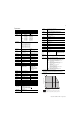
Wiring Connections for the Thermocouple/RTD Module
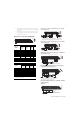
Example of 2, 3 and 4-wire RTD Wiring to a 1794-TB3
Terminal Base Unit
Example of 2, 3 and 4-wire RTD Wiring to a 1794-TB3T
Terminal Base Unit
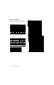
Example of Thermocouple Wiring to a 1794-TB3T
Ter minal Base Unit
Example of Grounded Thermocouple Wiring to a
1794-TB3T Terminal Base Unit
Example of Millivolt Wiring to a 1794-TB3, -TB3S or
-TB3T Terminal
Base Unit
RTD or mV
Channel
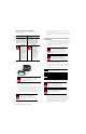
1794-TB2, -TB3 and -TB3S Terminal Base Units
High
Signal
Terminal
(H) or (+)
Low
Signal
Terminal
(L) or (-)
Signal
Return
1
(-IR8
only)
Shield
Return
0 A-0 A-1 B-17 B-18
1 A-2 A-3 B-19 B-20
2 A-4 A-5 B-21 B-22
3 A-6 A-7 B-23 B-24
4 A-8 A-9 B-25 B-26
5 A-10 A-11 B-27 B-28
6 A-12 A-13 B-29 B-30
7 A-14 A-15 B-31 B-32
24V dc Common B-16 thru 33
+24V dc Power -TB3, -TB3S (C-34 thru C-51); -TB2 (C-34 & C-51)
1 When using a 2-wire RTD, jumper the signal return to the low signal
terminal.
RTD, mV or
Thermocouple
1
Channel
1794-TB3T and -TB3TS Terminal Base Units
High Signal
Terminal
(H) or (+)
Low Signal
Terminal
(L) or (-)
Signal
Return
(-IR8 only)
Shield
Return
2
0 A-0 A-1 B-17 C-39
1 A-2 A-3 B-19 C-40
2 A-4 A-5 B-21 C-41
3 A-6 A-7 B-23 C-42
4 A-8 A-9 B-25 C-43
5 A-10 A-11 B-27 C-44
6 A-12 A-13 B-29 C-45
7 A-14 A-15 B-31 C-46
1 Terminals 36, 37 and 38 and 47, 48 and 49 are for cold junction compensation only,
(with 38 and 47 chassis GND).
2 Terminals 39 to 46 are chassis ground.
17 18 19 20 21 22 23 24 25 26 27 28 29 30 31 32 33
0 1 2 3 4 5 6 7 8 9 10 11 12 13 14 15
16
12 34567 891011121314150
35 36 37 38 39 40 41 42 43 44 45 46 47 48 49 50 51
34
1794-TB2, TB3, -TB3T
0-15
34-51
16-33
A
B
C
Shaded terminals not included on 1794-TB2 terminal base unit.
17 18 19 20 21 22 23 24 25 26 27 28 29 30 31 32 33
0 1 2 3 4 5 6 7 8 9 10 11 12 13 14 15
16
12 34567 891011121314150
35 36 37 38 39 40 41 42 43 44 45 46 47 48 49 50 51
34
1794-TB3
0 -15
34-51
16-33
4-Wire RTD 2-Wire RTD3-Wire RTD
Clip or tieback
4th lead.
Attention: Keep exposed area of inner conductor as short as possible.
A
B
C
When using a 2-wire RTD, jumper the signal return to the low signal terminal.
17 18 19 20 21 22 23 24 25 26 27 28 29 30 31 32 33
0 1 2 3 4 5 6 7 8 9 10 11 12 13 14 15
16
12 34567 891011121314150
35 36 37 38 39 40 41 42 43 44 45 46 47 48 49 50 51
34
1794-TB3T
0 -15
34-51
16-33
A
B
C
Clip or tieback
4th lead.
Attention: Keep exposed area of inner conductor as short as possible.
4-Wire RTD 2-Wire RTD3-Wire RTD
17 18 19 20 21 22 23 24 25 26 27 28 29 30 31 32 33
0 1 2 3 4 5 6 7 8 9 10 11 12 13 14 15
16
12 34567891011121314150
35 36 37 38 39 40 41 42 43 44 45 46 47 48 49 50 51
34
1794-TB3T
0 -15
34 - 51
16 - 33
+
_
CJC CJC
CJC kit Cat. No.
1794-CJC2/A
(contains 2 CJCs)
Channel 0 (Terminals 0 and 1 with shield to 39)
A
B
C
Ch. 4-7Ch 0-3
17 18 19 20 21 22 23 24 25 26 27 28 29 30 31 32 33
0 1 2 3 4 5 6 7 8 9 10 11 12 13 14 15
16
12 34567 891011121314150
35 36 37 38 39 40 41 42 43 44 45 46 47 48 49 50 51
34
1794-TB3T
0 -15
34 - 51
16 - 33
+
Channel 0
(Terminals 0 and 1
with shield to 39)
CJC CJC
CJC kit Cat. No.
1794-CJC2/A
(contains 2 CJCs)
When using grounded thermocouples, and the error is off the same
amount on each thermocouple, connect terminal 16 to ground, and
connect the thermocouple ground to the same ground,
A
B
C
_
Ch. 4-7Ch 0-3
17 18 19 20 21 22 23 24 25 26 27 28 29 30 31 32 33
0 1 2 3 4 5 6 7 8 9 10 11 12 13 14 15
16
1 2 3 4 5 6 7 8 9 10 11 12 13 14 150
35 36 37 38 39 40 41 42 43 44 45 46 47 48 49 50 51
34
1794-TB3 shown
0 –15
34–51
16–33
+
–
Millivolt input
Channel 1
Millivolt
Source
Channel 0 (T erminals 0, 1 and 17)
For more accurate readings, use the 1794-TB3T for mV measurement.