
Manual

6–5
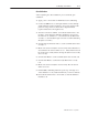
Calibrating Your Module
Publication
1794-6.5.7 – April 1997
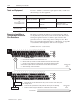
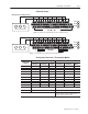
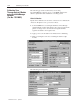
Calibration Setups
17 18 19 20 21 22 23 24 25 26 27 28 29 30 31 32 33
0 1 2 3 4 5 6 7 8 9 10 11 12 13 14 15
16
1 2 3 4 5 6 7 8 9 10 11 12 13 14 150
35 36 37 38 39 40 41 42 43 44 45 46 47 48 49 50 51
34
1794-TB2,
-TB3
0 –15
34–51
16–33
A
B
C
Precision Voltage Source
Using
a Precision V
oltage Source
CJC
17 18 19 20 21 22 23 24 25 26 27 28 29 30 31 32 33
0 1 2 3 4 5 6 7 8 9 10 11 12 13 14 15
16
1 2 3 4 5 6 7 8 9 10 11 12 13 14 150
35 36 37 38 39 40 41 42 43 44 45 46 47 48 49 50 51
34
1794-TB3T
0 –15
34–51
16–33
A
B
C
Precision Voltage Source
CJC CJC
Note 2: CJC not required if using thermocouple for resistance only.
Note: Use 1794-TB2 and -TB3 terminal base units for millivolt inputs only.
These terminals not on 1794-TB2
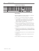
Wiring Connections for the Thermocouple Module
Thermocouple
1794-TB2, -TB3 Terminal Base Units 1794-TB3T Terminal Base Unit
2
Thermocouple
Channel
High Signal
Terminal (+)
Low Signal
Terminal (–)
Shield
Return
High Signal
Terminal (+)
Low Signal
Terminal (–)
Shield
Return
1
0 0 1 17 0 1 39
1 2 3 19 2 3 40
2 4 5 21 4 5 41
3 6 7 23 6 7 42
4 8 9 25 8 9 43
5 10 11 27 10 11 44
6 12 13 29 12 13 45
7 14 15 31 14 15 46
24V dc Common 16 thru 33 16, 17, 19, 21, 23, 25, 27, 29, 31 and 33
+24V dc power 1794-TB2 – 34 and 51; 1794-TB3 – 34 thru 51 34, 35, 50 and 51
1
Terminals 39 to 46 are chassis ground.
2
Terminals 36, 37, 38 and 47, 48, 49 are cold
junction compensator connections.