
Manual

6–3
Calibrating Your Module
Publication
1794-6.5.7 – April 1997
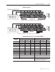
17 18 19 20 21 22 23 24 25 26 27 28 29 30 31 32 33
0 1 2 3 4 5 6 7 8 9 10 11 12 13 14 15
16
1 2 3 4 5 6 7 8 9 10 11 12 13 14 150
35 36 37 38 39 40 41 42 43 44 45 46 47 48 49 50 51
34
1794-TB3, -TB3T
0
–15
34–51
16–33
A
B
C
3
Thermocouple
or
Sensor
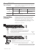
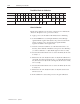
a.
Remove the decade box and voltage source.
b.
Reconnect the lead wires to the input terminals for this channel.
c.
Repeat this procedure for the remaining channels.
You must calibrate the module in a FLEX I/O system. The module
must communicate with the processor and a programming terminal.
You can calibrate input channels in any order, or all at once.
Before calibrating your module, you must enter ladder logic into the
processor memory, so that you can initiate BTWs to the module, and
read inputs from the module.
Important: In order to allow the internal module temperature to
stabilize, energize the module for at least 40 minutes
before calibrating.
Module calibration consists of:
• Applying a reference to the desired input(s).
• Sending a message to the module indicating which inputs to read
and what calibration step is being performed (offset).
The module stores this input data.
• Applying a second reference signal to the module, and sending a
second message indicating which inputs to read and what
calibration step is being performed (gain).
The module computes new calibration values for the inputs.
Once the calibration is complete, the module reports back status
information about the procedure.
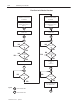
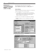
The following flow chart shows the procedure for calibration
Important: Perform the offset calibration procedure first, then the
gain calibration procedure.
Manually Calibrating your
Thermocouple/mV Input
Module