
Manual


5–5
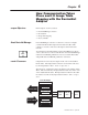
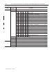
How Communication Takes Place and I/O Image Table Mapping with the DeviceNet Adapter
Publication
1794-6.5.7 – April 1997
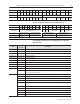
Description
Decimal
Bit
(Octal Bit)
Word
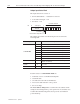
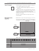
Read Word 11
continu
03 (03) Powerup bit – this bit is set (1) until configuration data is received by the module.
continu
ed
04–06 (04–06)
Critical Fault bits – If these bits are anything other than zero, return the module to the factory for repair.
07 (07) Unused – set to 0
08 (10) Calibration Range bit – set to 1 if a reference signal is out of range during calibration
09 (11) Calibration Done bit – set to 1 after an initiated calibration cycle is complete.
10 (12) Calibration Bad bit – set to 1 if the channel has not had a valid calibration.
11–15 (13–17) Unused – set to 0
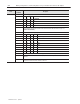
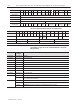
Write Word 1
00–01 (00–01) Module Data Type
Bit 01 00 Definition
0 0
o
C (default)
0 1
o
F
1 0 Bipolar counts scaled between –32768 and +32767
1 1 Unipolar counts scaled between 0 and 65535
Bit 02 (02) Fixed Digital Filter – When this bit is set (1), a software digital filter is enabled. This filter settles to
100% of a Full Scale step input in 60 times the selected first notch filter time shown on page 4–3.
Default – filter disabled.
03–05 (03–05) A/D Filter First Notch Frequency
Bit 05 04 03 Definition
0 0 0 10Hz (default)
0 0 1 25Hz
0 1 0 50Hz
0 1 1 60Hz
1 0 0 100Hz
1 0 1 250Hz
1 1 0 500Hz
1 1 1 1000hZ
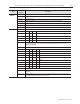
06 (06) Calibration High/Low bit – This bit is set during gain calibration; reset during offset calibration.
07 (07) Calibration clock – this bit must be set to 1 to prepare for a calibration cycle; then reset to 0 to initiate
calibration.
08–15 (10–17) Calibration mask – The channel, or channels, to be calibrated will have the correct mask bit set. Bit 8
corresponds to channel 0, bit 9 to channel 1, and so on.