
Manual


5–3
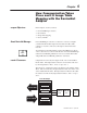
How Communication Takes Place and I/O Image Table Mapping with the DeviceNet Adapter
Publication
1794-6.5.7 – April 1997
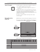
System throughput, from analog input to backplane, is a function of:
• the configured A/D filter first notch frequency
• the number of channels actually configured for connection to a
specific sensor
The A/D converter which converts channel 0 through 7 analog data
to a digital word provides a programmable first notch filter. You can
set the position of the first notch of this filter during module
configuration. The selection influences the A/D output data rate, thus
affecting system throughput.
The number of channels included in each input scan also affects
system throughput.
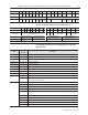
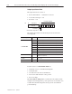
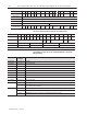
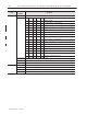
FLEX I/O thermocouple module data table mapping is shown below.
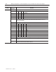
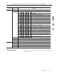
Thermocouple/mV Input Module (1794-IT8) Image Table Mapping
Module
Image
I/O Image
Input Data Channel 0
Input Data Channel 1
Input Data Channel 2
Input Data Channel 3
Input Data Channel 4
Input Data Channel 5
Input Data Channel 6
Input Data Channel 7
Underrange
Calibration Mask
Thermocouple Type
Input Size
Output Size
0 to 3 Words
1 to 11 Words
Reserved
Overrange
Calibration Status
Thermocouple Type
Configuration
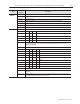
Thermocouple/mV Input Module (1794-IT8) Read
Dec.
Bit
15 14 13 12 11 10 09 08 07 06 05 04 03 02 01 00
Octal Bit 17 16 15 14 13 12 11 10 07 06 05 04 03 02 01 00
Read Word 1 Reserved
Read Word 2 Channel 0 Input Data
Read Word 3 Channel 1 Input Data
Read Word 4 Channel 2 Input Data
Read Word 5 Channel 3 Input Data
Read Word 6 Channel 4 Input Data
SEE
PAGE 4–3
System Throughput
Mapping Data into the
Image Table