
Manual

4–5
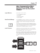
Writing Configuration to and Reading Status from your Module with a Remote I/O Adapter
Publication
1794-6.5.7 – April 1997
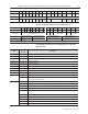
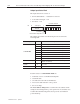
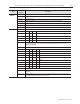
00010203040506070809101112131415Decimal
Bit
00010203040506071011121314151617Octal Bit
9 Overrange Bits Underrange Bits
10 0 0 0 0 0
Bad
Cal
Cal
Done
Cal
Range
0 Diagnostic Status
Pwr
Up
Bad
Structure
CJC
over
CJC
Under
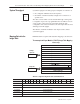
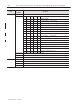
Thermocouple/mV Input Module (1794-IT8) Write
Dec.
Bit
15 14 13 12 11 10 09 08 07 06 05 04 03 02 01 00
Octal Bit 17 16 15 14 13 12 11 10 07 06 05 04 03 02 01 00
Write Word 0 8-Bit Calibration Mask
Cal
Clk
Cal hi
Cal lo
Filter Cutoff FDF Data Type
1 Thermocouple 3 Type Thermocouple 2 Type Thermocouple 1 Type Thermocouple 0 Type
2 Thermocouple 7 Type Thermocouple 6 Type Thermocouple 5 Type Thermocouple 4 Type
Where: FDF
= fixed digital filter bit
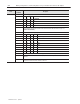
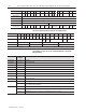
Word/Bit Descriptions for the 1794-IT8 Thermocouple/mV
Input Module
Word
Decimal
Bit
(Octal Bit)
Description
Read Word 0 00–15 (00–17) Reserved
Read Word 1 00–15 (00–17) Channel 0 Input data
Read Word 2 00–15 (00–17) Channel 1 Input data
Read Word 3 00–15 (00–17) Channel 2 Input data
Read Word 4 00–15 (00–17) Channel 3 Input data
Read Word 5 00–15 (00–17) Channel 4 Input data
Read Word 6 00–15 (00–17) Channel 5 Input data
Read Word 7 00–15 (00–17) Channel 6 Input data
Read Word 8 00–15 (00–17) Channel 7 Input data
Read Word 9
00–07 (00–07) Underrange bits – these bits are set if the input signal is below the input channel’s minimum range.
08–15 (10–17) Overrange bits – these bits are set if 1), the input signal is above the input channel’s maximum range,
or 2), an open detector is detected.
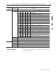
Read Word 10
00 (00) Cold Junction sensor underrange bit. – this bit is set if the cold junction temperature is below 0
o
C.
01 (01) Cold Junction sensor overrange bit. – this bit is set if the cold junction temperature is above 70
o
C.
02 (02) Bad Structure – this bit is set if an invalid thermocouple type is selected.
03 (03) Powerup bit – this bit is set (1) until configuration data is received by the module.
04–06 (04–06) Critical Error bits – If these bits are anything other than all zeroes, return the module to the factory for
repair
07 (07) Unused – set to 0
08 (10) Calibration Range bit – set to 1 if a reference signal is out of range during calibration
09 (11) Calibration Done bit – set to 1 after an initiated calibration cycle is complete.
10 (12) Calibration Bad bit – set to 1 if the channel has not had a valid calibration.
11–15 (13–17) Unused – set to 0