
Manual

4–3
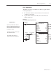
Writing Configuration to and Reading Status from your Module with a Remote I/O Adapter
Publication
1794-6.5.7 – April 1997
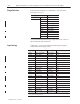
You select input scaling using the designated words of the write
block transfer instruction. Refer to the Bit/Word description for write
word 0, bits 00 and 01.
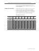
A hardware filter in the analog to digital converter lets you select a
frequency for the first notch of the filter. Selection of the filter
influences the analog to digital output data rate and changes the
module throughput. Module throughput is a function of the number
of inputs used and the first notch filter. Both of these influence the
time from a thermocouple input to arrival at the backplane.
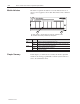
Throughput in Normal Mode
A/D Filter First Notch
Frequency
(effective resolution)
10Hz
(16-bits)
25Hz
(16-bits)
50Hz
(16-bits)
60Hz
(16-bits)
100Hz
(16-bits)
250Hz
(13-bits)
500Hz
(11-bits)
1000Hz
(9-bits)
Number of channels
scanned
System Throughput (in ms and s)
1 325 145 85 75 55 37 31 28
2 650 290 170 150 110 74 62 56
3 975 435 255 225 165 111 93 84
4 1.3s 580 340 300 220 148 124 112
5 1.625s 725 425 375 275 185 155 140
6 1.95s 870 510 450 330 222 186 168
7 2.275s 1.015s 595 525 385 259 217 196
8 2.60s
1
1.16s 680 600 440 296 248 224
1
Default
setting
Hardware First Notch Filter