
Manual

3–3
Module Programming
Publication
1794-6.5.7
PLC-5 Programming
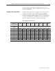
The PLC-5 program is very similar to the PLC-3 program with the
following exceptions:
1. Block transfer enable bits are used instead of done bits as the
conditions on each rung.
2. Separate block transfer control files are used for the block
transfer instructions.
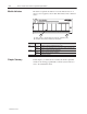
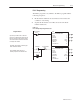
Figure 3.2
PLC-5 Family Sample Program Structure
BTR Enable Bit
EN
DN
BTW Enable Bit
1
2
ER
EN
DN
ER
BTR
BLOCK
TRANSFER READ
RACK:
GROUP:
MODULE:
DATA FILE:
LENGTH:
CONTINUOUS: N
BTW
BLOCK
TRANSFER WRITE
RACK:
GROUP:
MODULE:
LENGTH:
CONTINUOUS: N
2
1
0
N13:0
11
2
1
0
3
Program
Action
CONTROL:
N12:0
DATA FILE:
N13:20
CONTROL:
N12:5
N12:5
15
N12:0
15
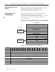
Thereafter, the program continuously per-
forms read block transfers.
Pushbutton
The pushbutton allows the user to
manually request a block transfer write.
N13:10
03
Power-up Bit
At power-up in RUN mode, or when the
processor is switched from PROG to RUN,
the user program enables a block transfer
read. Then it initiates a block transfer write
to configure the module.