
Manual

2–8
How to Install Your Thermocouple/mV Input Module
Publication
1794-6.5.7
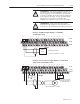
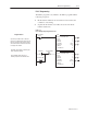
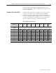
The thermocouple/mV module has one status indicator that is on
when power is applied to the module. This indicator has 3 different
states:
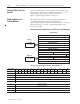
AB
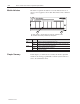
A = Status Indicator – indicates diagnostic results and configuration status
B = Insertable label for writing individual input designations
INPUT
0
INPUT 2 INPUT 4 INPUT 6INPUT 1 INPUT 3 INPUT 5 INPUT 7
THERMOCOUPLE INPUT 8 CHANNEL
3
1794–IT8
Allen-Bradley
+– +–
+– +–+– +
–
+–+–
OK
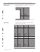
Color State Meaning
Red On Indicates a critical fault (diagnostic failure, etc.)
Blinking Indicates a noncritical fault (such as open sensor, input out of range, etc.)
Green On Module is configured and fully operational
Blinking Module is functional but not configured
Off Module not powered
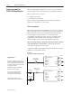
In this chapter, you learned how to install your thermocouple/mV
module in an existing programmable controller system and how to
wire to the terminal base units.
Module Indicators
Chapter Summary