
Manual

2–7
How to Install Your Thermocouple/mV Input Module
Publication
1794-6.5.7
!
ATTENTION: The thermocouple/mV modules do
not receive power from the backplane. +24V dc power
must be applied to your module before operation. If
power is not applied, the module position will appear
to the adapter as an empty slot in your chassis. If the
adapter does not recognize your module after
installation is completed, cycle power to the adapter.
!
ATTENTION: Total current draw through the
terminal base unit is limited to 10A. Separate power
connections to the terminal base unit may be necessary.
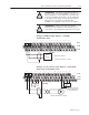
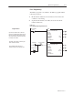
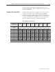
Example of Millivolt Input Wiring to a 1794-TB3
Terminal Base Unit
17 18 19 20 21 22 23 24 25 26 27 28 29 30 31 32 33
0 1 2 3 4 5 6 7 8 9 10 11 12 13 14 15
16
12 34567891011121314150
35 36 37 38 39 40 41 42 43 44 45 46 47 48 49 50 51
34
1794-TB3
0
–15
34–51
16–33
+
–
Millivolt input Channel 1
Millivolt
Source
Channel 0 (Terminals 0, 1 and 17)
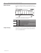
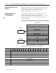
Example of 3-wire Thermocouple Wiring to a 1794-TB3T
Temperature Terminal Base Unit
17 18 19 20 21 22 23 24 25 26 27 28 29 30 31 32 33
0 1 2 3 4 5 6 7 8 9 10 11 12 13 14 15
16
12 34567891011121314150
35 36 37 38 39 40 41 42 43 44 45 46 47 48 49 50 51
34
1794-TB3T
0
–15
34–51
16–33
+
–
Channel 0 (Terminals 0, 1 and 39)
CJC CJC
Cold
Junction Compensator
Allen-Bradley PN 969424–01
(2 supplied with module)