
Manual

2–5
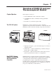
How to Install Your Thermocouple/mV Input Module
Publication
1794-6.5.7
Thermocouple/mV module wiring is made through the terminal base
unit on which the module mounts. The module comes with 2 cold
junction compensators for use when using the thermocouple module
in the thermocouple mode.
Compatible terminal base unit are:
Module 1794-TB2 1794-TB3 1794-TB3T
1
1794-IT8 Yes
2
Yes
2
Yes
1
The
1794-TB3T terminal base unit contains connections for cold junction
compensation for use with thermocouple modules.
2
For millivolt inputs only
.
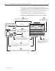
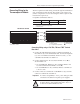
0 1 2 3 4 5 6 7 8 9 10 11 12 13 14 15
A
B
C
0 1 2 3 4 5 6 7 8 9 10 11 12 13 14 15
C N0 C N1 C N2 C CN3 C N4 C N5 C N6 C N7
VCJC CJCV
C
A
B
C
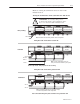
Where:
V = 24V dc
C = 24V dc common
N = additional input
CJC = cold junction compensation
= chassis ground
COM COM
VV
1794-TB2
and 1794-TB3
1794-TB3T
These
terminals on 1794-TB3 only
.
V = 24V dc
0
–15
34–51
16–33
COM
= 24V dc common
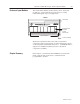
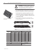
Connecting Wiring using a 1794-TB2, -TB3 and -TB3T Terminal
Base Units
1. Connect the individual signal wiring to numbered terminals on
the 0–15 row (A) on the terminal base unit. Connect the high side
(+) to the even numbered terminals, and the low side (–) to the
odd numbered terminals. See Table 2.A.
2. Connect shield return to the associated terminal on row B, as
shown in Table 2.A.
• On 1794-TB2 and -TB3 bases only: terminate shields to the
associated shield return terminals on row (B).
• On 1794-TB3T bases only: terminate shields to terminals 39
to 46 on row C.
3. Connect +24V dc to terminal 34 on the 34-51 row (C), and 24V
common to terminal 16 on the B row.
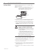
Important: To reduce susceptibility to noise, power analog modules
and discrete modules from separate power supplies.
!
ATTENTION: Do not daisy chain power or ground
from the thermocouple terminal base unit to any ac or
dc discrete module terminal base unit.
Connecting Wiring for the
Thermocouple/mV Module