
User Manual Manual

Publication 1794-6.5.12 - September 2011
Install Your FLEX I/O Input Module 19
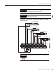
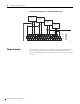
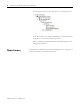
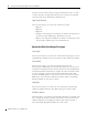
Example of 2-, 3- and 4-wire RTD and Thermocouple Wiring to a 1794-TB3G
Terminal Base Unit
IMPORTANT
Disconnecting and reconnecting RTDs or CJCs with power applied
temporarily disturbs the channel steady state data. Allow 2 minutes
for settling time after finishing connections.
IMPORTANT
If using RTD isolators, use 2- or 4-wire configurations only, and add
digital filtering to the inputs.
17 18 19 20 21 22 23 24 25 26 27 28 29 30 31 32
33
01 2 34567 89
10
11 12 13 14 15
16
1234567891011121314150
35 36 37 38 39 40 41 42 43 44 45 46
48
49 50 5134
1794-TB3G
0...15
34...51
16...33
A
B
C
4-Wire RTD Channel 3
2-Wire RTD Channel 1
3-Wire RTD Channel 2
+
-
CJC
Thermocouple Channel 4
1
2
2
1
1
3
2
1
1a
2a
2
47
45329
ATTENTION
Keep exposed area of inner conductor as short as possible.