FLEX I/O Thermocouple, RTD, and Millivolt Input Modules Catalog Numbers 1794-IRT8, 1794-IRT8K, 1794-IRT8XT User Manual
Important User Information Solid state equipment has operational characteristics differing from those of electromechanical equipment. Safety Guidelines for the Application, Installation and Maintenance of Solid State Controls (publication SGI-1.1 available from your local Rockwell Automation sales office or online at http://literature.rockwellautomation.com) describes some important differences between solid state equipment and hard-wired electromechanical devices.
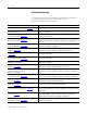
Summary of Changes This manual contains new and updated information. Changes throughout this revision are marked by change bars, as shown to the right of this paragraph. New and Updated Information This table contains the changes made to this revision.
iv Summary of Changes Notes: Publication 1794-6.5.
Table of Contents Summary of Changes New and Updated Information . . . . . . . . . . . . . . . . . . . . . . . . . . . . . . . iii Preface Who Should Use This Manual. . . . . . . . . . . . . . . . . . . . . . . . . . . . . . . . ix Purpose of the Manual. . . . . . . . . . . . . . . . . . . . . . . . . . . . . . . . . . . . . . ix About the Vocabulary . . . . . . . . . . . . . . . . . . . . . . . . . . . . . . . . . . . . . . ix Related Documentation. . . . . . . . . . . . . . . . . . . . . . . . . . . . .
vi Table of Contents Map Data for the Module . . . . . . . . . . . . . . . . . . . . . . . . . . . . . . . . . . . Thermocouple and RTD Input Module Image Table Mapping ........................................... Block Transfer Read and Write . . . . . . . . . . . . . . . . . . . . . . . . . . . Bit/Word Descriptions for the Input Module Block Transfer Read Words . . . . . . . . . . . . . . . . . . . . . . . . . . . . . . . . . . . . . . . . . . . Using Series A Functionality in a Series B Module . . . .
Table of Contents vii Appendix C Programming Your Module with PLC Family Processors Overview. . . . . . . . . . . . . . . . . . . . . . . . . . . . . . . . . . . . . . . . . . . . . . . . . 59 Enter Block Transfer Instructions. . . . . . . . . . . . . . . . . . . . . . . . . . . . . 59 PLC-2 Family Processor . . . . . . . . . . . . . . . . . . . . . . . . . . . . . . . . . 60 PLC-3 Family Processor . . . . . . . . . . . . . . . . . . . . . . . . . . . . . . . . . 60 PLC-5 Family Processor . . . . . . . .
viii Table of Contents Notes: Publication 1794-6.5.
Preface Read this preface to familiarize yourself with the rest of the manual. It provides information concerning: • • • • • who should use this manual the purpose of this manual related documentation conventions used in this manual terminology used in this manual Who Should Use This Manual We assume that you have previously used an Allen-Bradley programmable controller, that you are familiar with its features, and that you are familiar with the terminology we use.
x Preface Related Documentation The following documents contain additional information about Rockwell Automation products. To obtain a copy, contact your local Rockwell Automation office or distributor. Resource Description FLEX I/O Product Profile, publication 1794-PP019 xxxxx Comprehensive product profile for the FLEX I/O product line. FLEX I/O ControlNet Redundant Media Adapter, publication 1794-5.18 x xxxx Information on how to install the FLEX I/O ControlNet Redundant Media Adapter (1794-ACNR).
Preface Resource xi Description FLEX I/O 4 Isolated Input Module Installation Instructions, Information on how to install the FLEX I/O 4 Isolated Input Module publication 1794-IN038 x xxxxxxxxxxxxx (Catalog No. 1794-IF4I). FLEX I/O 2 In/2 Out Isolated Analog Combo Module Installation Instructions, publication 1794-IN039 x xxxxxxxxxxxxx Information on how to install the FLEX I/O 2 In/2 Out Isolated Analog Combo Module (Catalog No. 1794-IF2XOF2I).
xii Preface Resource Description FLEX I/O DC Power Supply Installation Instructions, publication 1794-IN069 x xxxxxxxxxxxxx Information on how to install the FLEX I/O DC Power Supply (Catalog No. 1794-PS13, 1794-PS3). Industrial Automation Wiring and Grounding Guidelines, publication 1770-4.1 x xxxxxxxxxxxxx In-depth information on grounding and wiring Allen-Bradley programmable controllers. Rockwell Automation Industrial Automation Glossary, AG-7.
Chapter 1 Overview of FLEX I/O and Your Thermocouple, RTD, and Millivolt Input Module This chapter provides a description of the FLEX I/O Thermocouple, RTD, and Millivolt Input module and an overview of how it communicates with programmable controllers.
2 Overview of FLEX I/O and Your Thermocouple, RTD, and Millivolt Input Module The FLEX system consists of an adapter module, terminal base unit, DIN rail, power supply, and adapter cabling components. You can use up to 8 terminal bases per adapter module. For detailed instructions on how to set up and install your module, refer to the topic, Install Your FLEX I/O Input Module, on page 7. Types of Modules The module refer to the following catalogs. Catalog No.
Overview of FLEX I/O and Your Thermocouple, RTD, and Millivolt Input Module The FLEX I/O Module in a Logix Control System 3 The FLEX I/O Thermocouple, RTD, and Millivolt modules are intelligent modules that interface analog signals with Rockwell Automation programmable controllers through a FLEX I/O adapter module. The adapter transfers data to and from the module.
4 Overview of FLEX I/O and Your Thermocouple, RTD, and Millivolt Input Module A broader view of how the FLEX I/O module interfaces with the different elements in a Logix system is shown in the sample illustration below. PC running controller and Rockwell Automation configuration software PanelView Station FLEX System 1794 adapter 1794 FLEX I/O module Bridge 45567 Ethernet In this example, the FLEX I/O module communicates with the controller through the adapter.
Overview of FLEX I/O and Your Thermocouple, RTD, and Millivolt Input Module 5 Module Label and Indicators 1794-IRT8 Module type Removable label 1794-IRT8 TC RTD INPUT 8 CHANNEL 3 IN 0 F IN 1 F IN 2 F IN 3 F IN 4 F IN 5 F IN 6 F IN 7 F PWR Keyswitch position indicator (#3) Power on indicator Input designators 45317 Chapter Summary In this chapter, you were introduced to the FLEX I/O system and the Thermocouple, RTD, and mV input module, and how it communicates with programmable controllers.
6 Overview of FLEX I/O and Your Thermocouple, RTD, and Millivolt Input Module Notes: Publication 1794-6.5.
Chapter 2 Install Your FLEX I/O Input Module Overview Before You Install Your Module This chapter provides you with pre-installation requirements and instructions on how to install your FLEX I/O Thermocouple, RTD, and Millivolt Input module.
8 Install Your FLEX I/O Input Module Series A and Series B The table, Series A and Series B Differences, describes the differences between Series A and Series B of the FLEX I/O Thermocouple, RTD, and mV Input modules.
Install Your FLEX I/O Input Module ATTENTION 9 Do not daisychain power or ground from the terminal base unit to any AC or DC digital module terminal base unit. Methods of wiring the terminal base units are shown in the illustration below.
10 Install Your FLEX I/O Input Module ATTENTION Note the following considerations for each type of wiring configuration: • Daisychain – AIl modules must be analog or TC, RTD, and mV modules for this configuration. • Individual – Use this type of of configuration for any "noisy" DC digital I/O modules in your system. • Combination – All modules powered by the same power supply must be analog or TC, RTD, and mV modules for the combination type of configuration.
Install Your FLEX I/O Input Module 11 2. Check to make sure that the 16 pins in the male connector on the adjacent device are straight and in line so that the mating female connector on this terminal base unit will mate correctly. 9 0 1 8 2 7 7 3 6 4 22 ++ 45319 Make certain that the female FlexBus connector is fully retracted into the base unit. 3. Position the terminal base at a slight angle and hooked over the top of the 35 x 7.5 mm DIN rail A (Allen-Bradley part number 199-DR1; 46277-3).
12 Install Your FLEX I/O Input Module 5. Rotate the terminal base onto the DIN rail with the top of the rail hooked under the lip on the rear of the terminal base. Use caution to make sure that the female FlexBus connector does not strike any of the pins in the mating male connector. 6. Press down on the terminal base unit to lock the terminal base on the DIN rail.
Install Your FLEX I/O Input Module 13 Mount on a Panel or Wall Installation of a FLEX system on a wall or panel consists of: • • • • laying out the drilling points on the wall or panel. drilling the pilot holes for the mounting screws. mounting the adapter mounting plate. installing the terminal base units and securing them to the wall or panel.
14 Install Your FLEX I/O Input Module 1. Lay out the required points on the wall or panel as shown in the drilling dimension drawing. Drilling Dimensions for Panel or Wall Mounting Millimeters (Inches) 35.5 (1.4) 58.5 (2.3) 35.5 (1.4) 58.5 (2.3) 35.5 (1.4) 21 (0.83) 45327 2. Drill the necessary holes for the #6 self-tapping mounting screws. 3. Mount the mounting plate for the adapter module using two #6 self-tapping screws – 18 screws included for mounting up to 8 modules and the adapter.
Install Your FLEX I/O Input Module 15 1. Rotate keyswitch (3) on terminal base unit (4) clockwise to position 3 as required for the module. Do not change the position of the keyswitch after wiring the terminal base unit. 2 3 1 4 5 6 7 8 40231 Label here or under here Description Description 1 FlexBus connector 5 Base unit 2 Latching mechanism 6 Alignment groove 3 Keyswitch 7 Alignment bar 4 Cap plug 8 Module 2.
16 Install Your FLEX I/O Input Module 6. Remove cap plug and attach another terminal base unit to the right of this terminal base unit if required. Make sure the last terminal base has the cap plug in place. IMPORTANT The adapter is capable of addressing eight modules. Do not exceed a maximum of eight terminal base units in your system. Wiring the module is done using the 1794-TB3G, 1794-TB3GK or the 1794-TB3GS terminal base units.
Install Your FLEX I/O Input Module 17 Signal wiring shields can be connected to terminals 16 or 33 on row B or terminals 40…45 on row C. 2. Connect the +V DC power lead to terminal 34 on row C, terminals 34…51. 3. Connect the -V DC common (return-) to terminal 35 on row C, terminals 34…51. ATTENTION Do not daisychain power or ground from this terminal base unit to any AC or DC digital module terminal base units. 4.
18 Install Your FLEX I/O Input Module RTD 1 Wiring Connections for the FLEX I/O Input Module 2 2-wire 3-wire Connect the following: Input types 1 3 2 RTD – 3-wire RTD – 4-wire 4-wire 1 + - 1 2 3 1 2 1a 2a 1 2 Thermocouple 1 2 Millivolt 1 2 (1) 2 1 Millivolt L RTD – 2-wire 1 1a 2a 2 Thermocouple H Shield(1) Terminals 37, 38 and 39 and 46, 47 and 48 are for cold junction compensation, with 38 and 47 as chassis GND.
Install Your FLEX I/O Input Module 19 Disconnecting and reconnecting RTDs or CJCs with power applied temporarily disturbs the channel steady state data. Allow 2 minutes for settling time after finishing connections. IMPORTANT If using RTD isolators, use 2- or 4-wire configurations only, and add digital filtering to the inputs.
20 Install Your FLEX I/O Input Module Example of Millivolt Wiring to a 1794-TB3G Terminal Base Unit Millivolt Source Millivolt Source + + Millivolt Source - + Millivolt Source + 0 1 16 17 34 2 3 18 35 19 36 4 3 2 1 0 20 37 5 4 21 38 6 5 6 22 39 7 8 9 10 11 12 7 8 9 10 11 12 23 40 24 41 25 42 26 43 27 44 28 45 13 14 13 29 46 - 30 47 15 15 14 31 48 32 49 33 50 51 0...15 A 16...33 B 34...51 C 45330 Chapter Summary Publication 1794-6.5.
Chapter 3 Configure Your FLEX I/O Module with RSLogix 5000 Software Overview This chapter describes how to configure the FLEX I/O Thermocouple, RTD, and mV module for the ControlLogix and CompactLogix system using the RSLogix 5000 software. The 1794-IRT8 module can communicate through different networks such as ControlNet, Ethernet, Profibus, among others. In the examples below, the Ethernet adapter is used for communication between the Logix processor and the FLEX I/O bus.
22 Configure Your FLEX I/O Module with RSLogix 5000 Software 1. In the I/O Configuration tree, right-click the 1794-AENT adapter, and select New Module. Right-click the local adapter module. Select New Module. 2. The Select Module dialog appears. Select the FLEX I/O module and click OK. 3. Complete the following fields in the New Module dialog that appears. Click OK. • Name • Description • Comm Format • Electronic Keying Publication 1794-6.5.
Configure Your FLEX I/O Module with RSLogix 5000 Software 23 4. Click the Connection tab. Specify a value for the Requested Packet Interval (RPI). 5. Click the Module Info tab to see Module Identification and Status information. These fields are populated when the module goes online. 6. Click the Input Configuration tab and specify the values for the following fields: • Channel • Sensor • Sensor Mode • Input Filter Cutoff • Data Format Publication 1794-6.5.
24 Configure Your FLEX I/O Module with RSLogix 5000 Software Configuration Parameters Field Name Description Configuration Options Sensor Allows you to select the main sensor function of your module, whether Thermocouple or RTD. You will need to configure your module based on this main configuration by specifying the next parameters. Thermocouple RTD Sensor Type Allows you to select one of nine thermocouple types or one of eight RTD types. Default unit is mV for thermocouples and ohms for RTDs.
Configure Your FLEX I/O Module with RSLogix 5000 Software 25 Configuration Parameters Field Name Description Configuration Options Sensor Mode Allows you to select the operational mode for the thermocouple or RTD inputs. For thermocouple inputs, you can choose the cold junction compensation mode. For RTD inputs, you can choose 2-wire, 2-wire with user selected RTD offset, 3-wire, and 4-wire. Default for thermocouples is external compensation; default for RTDs is 2-wire (with no offsets).
26 Configure Your FLEX I/O Module with RSLogix 5000 Software You should see the FLEX I/O module in the I/O Configuration tree. To be able to check if your configured parameters are acceptable and the configuration is successful, you need to go online. Refer to the RSLogix 5000 Online Help for detailed descriptions of the configuration parameters. Chapter Summary Publication 1794-6.5.
Chapter 4 Read and Write Configuration Maps for the FLEX I/O Module Overview Configure Your Input Module This chapter describes how to configure, read data from, and map data to your FLEX I/O Thermocouple, RTD, and mV Input module.
28 Read and Write Configuration Maps for the FLEX I/O Module microprocessor. The filter selections range from Hardware Only to 5 s time constant. The times are approximate because they are based on the module scan time, which varies. The default is Hardware Only. Data Format Selection This set of bits allows you to select one of these five formats: • Degree C • Degree F • Degree K • Unipolar – The end points for Unipolar are scaled to the end points of the thermocouple or RTD range.
Read and Write Configuration Maps for the FLEX I/O Module 29 Fault Mode You can enable or disable the fault detection. When enabled in thermocouple mode, each channel is monitored for an open circuit. If an open is detected, the overrange and fault bits are set for that channel, and the channel data is set to the maximum value (Series A), or minimum value (Series B) for the chosen mode of operation.
30 Read and Write Configuration Maps for the FLEX I/O Module RTD Type Thermocouple Type 120 Ω Nickel α = 0.00672 (-80…+320 °C) (-112…608 °F) R -50…1768 °C (-58…3214 °F) 10 Ω Copper α = 0.00427 (-200…+260 °C) (-328…500 °F) S -50…1768 °C (-58…3214 °F) T -270…400 °C (-454…752 °F) You select individual channel ranges using write word 1 of the block transfer write instruction.
Read and Write Configuration Maps for the FLEX I/O Module 31 module uses up to 11 words of input data and up to 4 words of output data. Each word is composed of 16 bits. Thermocouple and RTD Input Module Image Table Mapping Module Image Input Data Channel 0 Input Data Channel 1 I/O Image Input Size Input Data Channel 2 Input Data Channel 3 1...
32 Read and Write Configuration Maps for the FLEX I/O Module Input Map (Block Transfer Read) Dec. 15 14 13 12 11 10 09 08 07 06 05 04 03 02 01 00 Oct. 17 16 15 14 13 12 11 10 07 06 05 04 03 02 01 00 Word 6 Channel 6 Input Data Word 7 Channel 7 Input Data Word 8 Overrange Alarm Bits (channel 0 = bit 8, and so on.
Read and Write Configuration Maps for the FLEX I/O Module 33 Read Word 3 00…15 (00…17) Channel 3 Input data Read Word 4 00…15 (00…17) Channel 4 Input data Read Word 5 00…15 (00…17) Channel 5 Input data Read Word 6 00…15 (00…17) Channel 6 Input data Read Word 7 00…15 (00…17) Channel 7 Input data Read Word 8 00…07 Underrange bits – these bits are set if the input signal is below the minimum range of the input channel. Bit 00 corresponds to channel 0…bit 07 corresponds to channel 7.
34 Read and Write Configuration Maps for the FLEX I/O Module Word Dec. Bits (Octal Bits) Description Read Word 10 00…07 Extended data table data response bits – These bits echo the EDT command data written to the module during calibration. 08…14 (10…16) Extended data table command response bits – These bits echo the EDT command written to the module during calibration. 15 (17) Reserved for factory use Bit/Word Descriptions for Block Transfer Write Words Word Dec.
Read and Write Configuration Maps for the FLEX I/O Module 35 Bit/Word Descriptions for Block Transfer Write Words Word Dec. Bits (Octal Bits) Description Write Word 0 (continued) Bits 08…11 (10…13) Bit 11 10 09 08 Data type for channels 0…7 0 0 0 0 °C (implied decimal point xxxx.x) 0 0 0 1 °F (implied decimal point xxxx.x) 0 0 1 0 °K (implied decimal point xxxx.
36 Read and Write Configuration Maps for the FLEX I/O Module Bit/Word Descriptions for Block Transfer Write Words Word Dec. Bits (Octal Bits) Description Write Word 1 (continued) 0 0 External compensation – uses cold junction sensors. Both CJC sensors must be used when external compensation is selected. 0 1 Internal compensation – uses the user selected Reference Junction Selection. 1 0 No compensation. Data is referenced to 0 °C (32 °F).
Read and Write Configuration Maps for the FLEX I/O Module 37 Bit/Word Descriptions for Block Transfer Write Words Word Dec. Bits (Octal Bits) Description 1 0 0 1 T -270…400 °C (-454…752 °F) 1010…1111 not used Bits 12…13 (14…15) Sensor Mode Select bits Bit 13 12 Sensor mode select for channels 4…7 Thermocouple 0 0 External compensation – uses cold junction sensors. Both CJC sensors must be used when external compensation is selected.
38 Read and Write Configuration Maps for the FLEX I/O Module Bit/Word Descriptions for Block Transfer Write Words Word Dec. Bits (Octal Bits) Description Write Word 3 00…07 Extended data table data bits – These bits are written to the module during calibration. They are used to define offset, gain and general channel calibration. 08…14 (10…16) Extended data table command bits – These bits are written to the module during calibration. They are used to select channel calibration action.
Chapter 5 Calibrate Your Module Overview When and How to Calibrate Your FLEX I/O Module This chapter provides the tools and equipment, and procedure for calibrating your FLEX I/OThermocouple, RTD, and mV input module.
40 Calibrate Your Module Tools and Equipment Calibrate Your Input Module To calibrate your Thermocouple, RTD, and mV input module, you will need the following tools and equipment: Tool or Equipment Description Precision Resistors High Precision Resistors: 383 W, 0.01%, 5ppm/°C 100 W, 0.01%, 5ppm/°C 10 KΩ, 0.
Calibrate Your Module 41 Calibration Setup Using Precision Resistors for 383 Ω and 100 Ω calibration 0 1 0 1 17 16 2 3 4 5 6 7 8 2 3 4 5 6 7 8 18 34 19 35 20 36 21 37 22 38 23 39 24 40 9 9 25 41 10 11 12 10 11 12 26 42 27 43 28 44 13 14 13 29 45 30 46 15 14 15 31 47 32 48 33 49 50 51 Using Precision Voltage Source for offset and gain calibration + - 0 1 2 3 4 5 6 7 0 1 2 3 4 5 6 7 16 17 34 18 35 19 36 20 21 37 38
42 Calibrate Your Module Wiring to the 1794-TB3G and 1794-TB3GS Terminal Base Units RTD or 1794-TB3G and 1794-TB3GS Terminal Base Units(1) Thermocouple High Signal Low Signal RTD Source Signal Return Channel Terminal (H) Terminal (L) Current (+) (-) 7 30 24V DC Power 34 and 50 24V DC Common 35 and 51 (1) 31 29 32 Terminals 16, 33 and 40…45 are chassis ground. Read and Write Words for Calibration The following tables provide read and write words for module calibration.
Calibrate Your Module 43 Read Words for Calibration Decimal 15 14 13 12 11 10 09 08 07 06 05 04 03 02 01 00 Octal 17 16 15 14 13 12 11 10 07 06 05 04 03 02 01 00 Word⇓ Read 5 Channel 5 Input Data 6 Channel 6 Input Data 7 Channel 7 Input Data 8 Overrange Alarm Bits (channel 0 = bit 08, and so on.) Underrange Alarm Bits (channel 0 = bit 00, and so on.
44 Calibrate Your Module EDT Calibration Command and Command Data Summary Config Word 3 Meaning EDT Command bits 8…15 Config Word 3 Config Word 3 Meaning bits 4…7 bits 0…3 Dec. (Hex) Channel No.
Calibrate Your Module Config Word 3 Meaning EDT Command bits 8…15 45 Config Word 3 Config Word 3 Meaning bits 4…7 bits 0…3 1 1 gain = 2, input = 0.0 mV 1 2 gain = 4, input = -50 mV 1 3 gain = 8, input = -10.0 mV 1 4 gain = 16, input = -9 mV 1 5 gain = 32, input = 1.
46 Calibrate Your Module EDT Commands for Offset Calibration All Channels Single Channel EDT Command EDT Data Command Dec. or Hex Dec. or Hex Bits 8…15 Decimal Bits Bits 4…7 0…3 EDT Command Gain Input (mV) Selected Hex 8 -10.00 + 0.008 mV 2413 9235 05 0…7 3 16 -9.00 + 0.004 mV 2414 9236 05 0…7 4 32 1.000 + 0.002 mV 2415 9237 05 0…7 5 3. Initiate a write to the module with the appropriate value in the EDT command location (write word 3, bits 00…15), as shown above. 4.
Calibrate Your Module 47 EDT Commands for Gain Calibration All Channels Single Channel EDT Command Data EDT Dec. or Hex Command Dec. or Hex Decimal Bits Bits Bits 8…15 4…7 0…3 EDT Command Gain Input (mV) Selected Hex 1 -320.00 + 0.064 mV 2420 9248 06 0…7 0 2 320.00 + 0.032 mV 2421 9249 06 0…7 1 4 110 + 0.016 mV 2422 9250 06 0…7 2 8 70.00 + 0.008 mV 2423 9251 06 0…7 3 16 29.00 + 0.004 mV 2424 9252 06 0…7 4 32 19.00 + 0.002 mV 2425 9253 06 0…7 5 2.
48 Calibrate Your Module 3. Initiate a write to the module with 2401 (hex) value in EDT command location (word 3, bits 00…15), as shown, for calibrating all channels at once. For individual channel calibrations, use the 04X1 (hex) (0401, 0411, 0421, ...0471 hex). 4. Monitor the EDT response location (read word 10, bits 00…15) for an echo of the EDT command. If the EDT response word reads 80FF (hex), repeat step 3. Make sure to allow for sufficient time for the module to respond to your request.
Calibrate Your Module 49 Cold Junction Calibration Both cold junction compensation inputs must be calibrated at at the same time. To calibrate both at once, proceed as follows: 1. Connect 10 KΩ, 0.5% resistors across terminals 37 and 39 (CJC 1) and terminals 46 and 48 (CJC 2). 2. Apply power to the module for 20 minutes before calibrating. 3. Initiate a write to the module with 2404 (hex) value in the EDT command location (word 3, bits 00…15). 4.
50 Calibrate Your Module Notes: Publication 1794-6.5.
Chapter 6 Troubleshoot the Module Overview This chapter provides a description of the different status indicators for the FLEX I/O Thermocouple, RTD, and mV module to help you troubleshoot. Module Indicators The FLEX I/O module has one status indicator (PWR) that is On when power is applied to the module, and one fault indicator (F) for each input.
52 Troubleshoot the Module Status Indicators Indicator Color Power Green State Description Blinking (when faults are enabled, and bit set) Indicates a noncritical fault (such as open sensor). Input data set to maximum, and indicator flashes at about 1 Hz rate. Off Module not powered On Module receiving power The FLEX I/O Thermocouple, RTD, and mV module returns diagnostics to the processor in Word 9 of the block transfer read (BTR) file.
Appendix A Specifications Overview This appendix contains general and environmental specifications and certifications for the FLEX I/O Thermocouple, RTD, mV Input Modules. General Specifications Attribute Value Number of inputs 8 channels (2 groups of 4) Module location Cat. Nos.
54 Specifications General Specifications Attribute Value Isolation voltage (continuous voltage withstand rating) 50V (continuous), Basic Insulation Type Type tested @ 1365V AC for 60 s, between field side and system No isolation between individual channels System throughput (8 channels scanned) – Add 0.5 ms if filtering is selected Typical module timing is shown here.
Specifications 55 General Specifications Attribute Value Temperature code, North American T4A Enclosure type rating None (open-style) Wire size Determined by installed terminal base Signal conductors Thermocouple Millivolt Wire type Use appropriate shielded thermocouple wire(2) Belden 8761 Shielded on signal ports Wiring category(1) 2 – on signal ports 3 – on power ports Terminal screw torque for cage-clamp terminal base Determined by installed terminal base (1) Refer to the thermocouple ma
56 Specifications Environmental Specifications Attribute Value Radiated RF immunity IEC 61000-4-3: 10V/m with 1 kHz sine-wave 80% AM from 80…2000 MHz 10V/m with 200 Hz 50% Pulse 100% AM at 900 MHz 10V/m with 200 Hz 50% Pulse 100% AM at 1890 MHz 3V/m with 1 kHz sine-wave 80% AM from 2000…2700 MHz EFT/B immunity IEC 61000-4-4: ±2 kV at 5 kHz on power ports ±2 kV at 5 kHz on shielded signal ports Surge transient immunity IEC 61000-4-5: ±2 kV line-earth(CM) on shielded signal ports Conducted RF immuni
Appendix B Electronic Data Sheet (EDS) Files Overview EDS provides the definition for a device’s configurable parameters and public interfaces to those parameters. Every type of configurable device has its own unique EDS. It is a simple text file that allows product-specific information to be made available to third-party vendors. This makes updating of configuration tools easier without having to constantly revise the configuration software tool.
58 Electronic Data Sheet (EDS) Files To acquire EDS files for Rockwell Automation and Allen-Bradley devices, go to Tools & Resources EDS Files at www.ab.com/networks/eds. It allows you to search for devices by the type of network and their catalog number. •Make sure to match the major firmware revision of the device as each major firmware revision is associated with a specific EDS file.
Appendix C Program Your Module with PLC Family Processors Overview This Appendix serves as a reference to users of the PLC-* Family Processors to program their modules. To initiate communication between the Thermocouple, RTD, and Millivolt modules and your PLC processor, you must enter block transfer instructions into your ladder logic program. Use this chapter to enter the necessary block transfer instructions into your ladder logic program.
60 Program Your Module with PLC Family Processors PLC-2 Family Processor The 1794 Thermocouple, RTD, and Millivolt modules are not recommended for use with PLC-2 family programmable controllers due to the number of digits needed for high resolution. IMPORTANT The Thermocouple, RTD, and Millivolt modules function with reduced performance in PLC-2 systems.
Program Your Module with PLC Family Processors PLC-3 Processor Program Example 61 Rung M:0 The IRT8 module is located in rack 3, I/O group 2, slot 1. The control file is a 10 word file starting at B17:0 that is shared by the BTR/BTW. The data obtained by the PLC3 processor is placed in memory starting at location N18:101, and with the default length of 0, is 11 words long.
62 Program Your Module with PLC Family Processors PLC-5 Processor Rung 2:0 Program Example The IRT8 module is located in rack 2, I/O group 2, slot 1. The integer control file starts at N22:200, is 5 words long and is compatible with all PLC-5 family members. The data obtained by the PLC-5 processor from the IRT8 module is placed in memory starting at N22:101, and with the default length of 0, is 11 words long.
Program Your Module with PLC Family Processors PLC-5/250 Processor Program Example 63 Rung 1STEPO:1 The IRT8 module is located in rack 14, I/O group 1, slot 0. The data obtained by the PLC-5/250 processor from the IRT8 module is placed in the data table starting at 2BTD5:101, and with the default length of 0, is 11 words long. The length can be any number between 0 and 11.
64 Program Your Module with PLC Family Processors Notes: Publication 1794-6.5.
Appendix D Safety Approvals European Hazardous Location Approval The 1794-IRT8, 1794-IRT8K, and 1794-IRT8XT modules are European Hazardous Location approved.
66 Safety Approvals North American Hazardous Location Approval The 1794-IRT8, 1794-IRT8K, and 1794-IRT8XT modules are North American Hazardous Location approved. The following information applies when operating this equipment in hazardous locations. Informations sur l’utilisation de cet équipement en environnements dangereux. Products marked “CL I, DIV 2, GP A, B, C, D” are suitable for use in Class I Division 2 Groups A, B, C, D, hazardous locations and nonhazardous locations only.
Index Numerics 1756-CNB 57 1756-ENBT 21 1794-ACN15 3 1794-ACNR15 3 1794-ACNR15K 3 1794-ADN 3 1794-AENT 3, 22 1794-APB 3 1794-APBDPV1 3 1794-ASB 3 1794-CJC2 2, 54 1794-IRT8 ix, 2, 4, 8, 21, 38, 71, 72 1794-IRT8K ix, 2, 71, 72 1794-IRT8XT ix, 2, 71, 72 1794-TB3G 7, 14, 15, 16, 18, 38, 39, 53, 54 1794-TB3GK 15, 16, 18, 53, 54 1794-TB3GS 7, 14, 15, 16, 18, 38, 39, 53, 54 A accuracy 65 adapter 1, 2, 12, 14 alignment bar 15 groove 15 Allen-Bradley 40, 71 analog signals 3 B backplane 7, 15 base unit 15 Belden 87
68 Index channel loop 29 CJC 30 differential 25 external 25, 36, 37 internal 25, 36, 37 conductors 55 configuration data format selection 28 fault mode 29 input filter 27 input range 27 input types 28 options 27 parameters 24 reference junction 28 RTD offset 29 sensor mode 28 sensor type 28 connecting wiring 41 connector current 54 female 10 male 10 controller 21 ControlLogix 21, 57 ControlNet 4, 8, 21 C-Tick 56 current draw 8 current source calibration 47 D daisychain 9, 17 data format bipolar 28 unipol
Index humidity 39 I indicator 54 input channels 40 default 28 designators 5 filter 24, 25 range 30 resistive 2 type 36, 37 installation connecting wiring 10 hazardous location 15 instructions 7 mounting 10 requirements 7 terminal base 12 IP54 protection 71 isolation mode 8 K keyswitch 7, 14, 15, 54 L ladder logic 40, 59 latching mechanism 15 Logix system 4 loop compensation 37 low pass 28 M male connector 10 manual conventions xii purpose ix related x manual calibration 40 message fault 40 millivolt 28
70 Index type K 24, 67 type N 24, 69 type R 24, 68 type S 24, 68 type T 24, 69 type TXK/XKL(L) 24, 70 RF immunity 56 RSLinx 57, 58 RSLogix 5000 software 4, 8, 21, 57 RSLogix 5 software 57 RSNetworx 57, 58 RTD analog input mapping 31 2-wire 18, 36, 37 3-wire 18, 25, 36, 37 3-wire connection 17 4-wire 18, 25, 36, 37, 41 4-wire connection 17 disconnecting 19 fault mode 29 isolators 19, 30 loop channel compensation 44 mode 29 offset 29, 32, 37, 42 wire pairs 17 S Safety Extra Low Voltage (SELV) 56 sensor CJC
Index troubleshoot 51 U unipolar 27 V vibration 55 voltage supply 54 W wire type 55 wire pairs 3-wire RTD 17 4-wire RTD 17 71 connecting 17 wiring category 55 combination 9 connections 18, 41 terminal base 8, 41 write words data format 42 filter time constants 34 input type 36 RTD Type 35 sensor mode 37 sensor type 36 Z Zone 2 71 Publication 1794-6.5.
72 Index Notes: Publication 1794-6.5.
Index 73 Publication 1794-6.5.
Rockwell Automation Support Rockwell Automation provides technical information on the Web to assist you in using its products. At http://www.rockwellautomation.com/support/, you can find technical manuals, a knowledge base of FAQs, technical and application notes, sample code and links to software service packs, and a MySupport feature that you can customize to make the best use of these tools.