$ # " " ! " ! $
Important User Information Because of the variety of uses for the products described in this publication, those responsible for the application and use of this control equipment must satisfy themselves that all necessary steps have been taken to assure that each application and use meets all performance and safety requirements, including any applicable laws, regulations, codes and standards. The illustrations, charts, sample programs and layout examples shown in this guide are intended solely for example.
Purpose of this Manual Audience This manual shows you how to use your FLEX I/O pulse counter module with Allen-Bradley programmable controllers. The manual helps you install, program and troubleshoot your module. You must be able to program and operate an Allen-Bradley programmable controller to make efficient use of your FLEX I/O module. In particular, you must know how to program block transfers. We assume that you know how to do this in this manual.
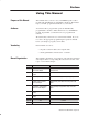
P–2 Using This Manual Conventions We use these conventions in this manual: In this manual, we show: Like this: 1' 1 1'$/$ (0 +-/$ (,%-/+ 1(-, !-21 1-.(" (, ,-1'$/ "' .1$/ (, 1'(0 + ,2 * 1' 1 1'$/$ (0 +-/$ (,%-/+ 1(-, !-21 1'$ 1-.
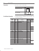
Using This Manual Publications Catalog Number Voltage 9 " '& 54054 3/,$4(' .$,/) /'5,( 9 9 " '& .054 3/,$4(' .$,/) /'5,( 9 9 # " '& .054 54054 3/,$4(' .$,/) /'5,( 9 9 " '& .054 .$,/) /'5,( 9 9 9 " '& *(2-/&/50,( .054 /'5,( 9 9 9 " '& *(2-/&/50,( .054 /'5,( 9 9 9 " '& 2(15(.&8 .
P–4 Using This Manual
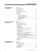
Table of Contents Overview of the Pulse Counter Module Chapter 1 What This Chapter Contains . . . . . . . . . . . . . . . . . . . . . . . . . . . . . How You Use the Pulse Counter Module . . . . . . . . . . . . . . . . . . . . . . . . . . . . . . What the Pulse Counter Module Does . . . . . . . . . . . . . . . . . . . . . . Typical Applications . . . . . . . . . . . . . . . . . . . . . . . . . . . . . . . . . . . Input Capabilities . . . . . . . . . . . . . . . . . . . . . . . . . . . . . . . . . . . . .
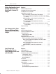
ii Table of Contents Writing Configuration to and Reading Status from Your Module with a Remote I/O Adapter Chapter 4 How Communication Takes Place and I/O Image Table Mapping with the DeviceNet Adapter Chapter 5 Input, Output and Configuration Files for Analog Modules when used with ControlNet Publication 1794ĆUM016B-EN-P - August 2002 What This Chapter Contains . . . . . . . . . . . . . . . . . . . . . . . . . . . . . 4-1 Configuring Your Pulse Counter Module . . . . . . . . . . . . . . . . . . .
iii Table of Contents /'-! */).!, * /'! 1 ( #! '! ++%)# %. *, !"%)%.%*)- "*, '* & , )-"!, ! *, - "*, .$! /'-! */).!, * /'! Troubleshoot the Pulse Counter Module Chapter 7 Specifications Chapter 8 $ . $%- $ +.!, *). %)- . ./- ) % .*,- $ . - !0.
Table of Contents
What This Chapter Contains How You Use the Pulse Counter Module Read this chapter to familiarize yourself with the 1794–IP4 module. For information on See page #) #( & ' (!& #("' % # (! ' ' (!& #("' % # (! # & "$(' $ ! ' & The 1794–IP4 module is an intelligent I/O module designed to perform high speed pulse counting.
1–2 Overview of the Pulse Counter Module (',*(& (* ),( (-)&!*+ $, (-',!* $, (-',!* $, (-',!* $, (-',!* + (#$ $, (-',!* + (#$ $, (-',!* (#$ -+ ',!*" ! !*$ & -+ (#$ $, (-',!* $, (-',!* 12-24V dc 0V . '$ &&/ +(& ,! ('.!*,!* Internal +5V dc Configuration is selected by setting A (below) in the appropriate position (variable SelectMeasureType).
Overview of the Pulse Counter Module What the Pulse Counter Module Does 1–3 The Pulse Counter module performs high-speed scaling calculation operations for various industrial applications. The module interfaces with a FLEX I/O family adapter which then communicates with a programmable controller processor that has block-transfer capability and external I/O devices.
1–4 Overview of the Pulse Counter Module Typical Applications You can use the 1794–IP4 module in the power management, automotive, food and beverage, and oil and gas industries for various flow and/or turbine metering applications. Some sample applications include: • • • • Input Capabilities quantity counting speed calulations brewery flow monitoring petrochemical flow and custody transfer The Pulse Counter module has 4 identical input interfaces.
Overview of the Pulse Counter Module 1–5 Start Period Time Measurement The control bit StartMeasurement starts the measurement of the time period. Function ' $ ) " " (*' " #) ()$%% #$) # ! ' $ ) " " (*' " #) () ')( $# ) %$( ) + $ ) + ' ! Check if the Measurement is Complete After a complete measurement the flag MeasurementReady is set.
1–6 Overview of the Pulse Counter Module Select Number of Periods The number of periods to be measured can be selected using the variable NumberofPeriods.
What This Chapter Contains Before You Install Your Input Module In this chapter, we tell you about: For information on See page "#+." +1 */0 (( +1. +!1(" 1.+," * *&+* &." 0&2"/ +3". "-1&.")"*0/ */0 ((&*$ 0%" +!1(" +* .
2–2 How to Install Your Pulse Counter Module Low Voltage Directive This product is tested to meet Council Directive 73/23/EEC Low Voltage, by applying the safety requirements of EN 61131–2 Programmable Controllers, Part 2 – Equipment Requirements and Tests. For specific information required by EN 61131-2, see the appropriate sections in this publication, as well as the following Allen-Bradley publications: • Industrial Automation Wiring and Grounding Guidelines For Noise Immunity, publication 1770-4.
How to Install Your Pulse Counter Module 2–3 Methods of wiring the terminal base units are shown in the illustration below. Wiring the Terminal Base Units (1794ĆTB3G shown) ! ATTENTION: Do not daisy chain power or ground from the terminal base unit to any ac or dc digital module terminal base unit. DaisyĆchaining .%, (.'- + ( .% .%, (.'- + ( .% & ( .% .%, (.'- + ( .% Note: %% &( .% , &.,- ).%, !+ *. ' 0 (+ & &( .% , !(+ -#$, ('!$".
2–4 How to Install Your Pulse Counter Module Installing the Module Installation of the Pulse Counter module consists of: • mounting the terminal base unit • installing the module into the terminal base unit • installing the connecting wiring to the terminal base unit If you are installing your module into a terminal base unit that is already installed, proceed to “Mounting the Pulse Counter Module on the Terminal Base” on page 2–7.
How to Install Your Pulse Counter Module 2–5 ' ' %! " & (" ' #) % ' ' "&' ' $' % &(% ' ## #" ' ' %! " & & & (" % ' # ' $' % " ' + (& #"" '#% & ( , % '% ' % && #*" #" ' ' %! " & (" ' '# # ' ' %! " & #" ' % ' ' %! " & # & "#' # "'# $ (& & % * % ) % #% & ! % ) '# #$ " ' # " ' $% && #*" #" ' ' %! " & ("' (& * ' ' % " % & ' # " ' '# # ' &
2–6 How to Install Your Pulse Counter Module 5. Repeat the above steps to install the next terminal base.
How to Install Your Pulse Counter Module 2–7 Drilling Dimensions for Panel/Wall Mounting of FLEX I/O Inches (Millimeters) 2. Drill the necessary holes for the #6 self-tapping mounting screws. 3. Mount the mounting plate (1) for the adapter module using two #6 self-tapping screws (18 included for mounting up to 8 modules and the adapter). Important: More Make certain that the mounting plate is properly grounded to the panel.
2–8 How to Install Your Pulse Counter Module 2. Make certain the flexbus connector (3) is pushed all the way to the left to connect with the neighboring terminal base/adapter. You cannot install the module unless the connector is fully extended. 3. Make sure that the pins on the bottom of the module are straight so they will align properly with the connector in the terminal base unit. ! ATTENTION: Remove field-side power before removing or inserting the module.
How to Install Your Pulse Counter Module Connecting Wiring for Your Pulse Counter Module 2–9 Wiring to the module is made through the terminal base unit on which the module mounts.
2–10 How to Install Your Pulse Counter Module 3. If using shielded cable, terminate the shield at the DIN rail (earth ground). 4. Connect +24V dc to terminal 34 on the 34-51 row (C). 5. Connect dc return to terminal 16 on the 16–33 row (B). ! ATTENTION: To reduce susceptibility to noise, power frequency modules and digital modules from separate power supplies. Do not exceed a length of 33 ft (10m) for dc power cabling. 6.
How to Install Your Pulse Counter Module 2–11 Wiring to a 1794ĆTBN or ĆTBNF Terminal Base Unit 1. Connect individual input wiring (N+, N–,) or (D+, D–) to the even numbered terminals on row (B) as indicated in the table below. ATTENTION: Do not connect maximum input voltage simultaneously to all inputs if the module ambient temperature is expected to exceed 40oC.
2–12 How to Install Your Pulse Counter Module Wiring connections for the 1794-IP4 Pulse Counter Module Channel Terminal Base Units 1794-TB2, -TB3, -TB3S Signal Name1 Signal 0V dc 12/24V dc (Common) Terminal Base Units 1794-TBN, -TBNF2 Signal Input 16-bit Period Time Measurement 32-bit Period Time Measurement "! ,**,+ "! #.
How to Install Your Pulse Counter Module 2–13 Example of 16-bit Period Time Measurement and 16-bit Accumulating Pulse Counter Wiring (4 channels) Accumulating Pulse Counter Channel 3 N N Channel 2 N N Channel 1 N N Channel 0 N N "&%$ (% # !' # &"" ) A B C & % ! * & &$%
2–14 How to Install Your Pulse Counter Module Example of 32-bit Period Time Measurement Wiring (4 channels) 32-bit period time measurement Channel 3 D D Channel 2 D D Channel 1 D D Channel 0 D D "&%$ (% # !' # &"" ) & % ! * & &$% A B C
How to Install Your Pulse Counter Module Module Indicators 2–15 The Pulse Counter module has one status indicator (PWR) that is on when power is applied to the module, an input on indicator for each channel, and an input status indicator for each input (8 in all). 4 CH PULSE COUNTER MODULE C B A A = Power/status indicator – Red – indicates initialization of internal logic at powerup Green – indicates initialization of internal logic is complete and correct.
What This Chapter Contains To initiate communication between the Pulse Counter module and your PLC processor, you must enter block transfer instructions into your ladder logic program. Use this chapter to enter the necessary block transfer instructions into your ladder logic program.
3–2 Programming Your Pulse Counter Module PLCĆ2 Family Processor The 1794 Pulse Counter module is not recommended for use with PLC-2 family programmable controllers due to the number of digits needed for high resolution. Important: The Pulse Counter module functions with reduced performance in PLC-2 systems.
Programming Your Pulse Counter Module PLCĆ5 Processor Program Example 3–3 60* !+( /1'6.( ,4 .1&$5(' ,0 3$&- *3162 4.15 !+( ,05(*(3 &10531. ),.( 45$354 $5 !+( '$5$ 4(05 %8 5+( 9 231&(4413 51 5+( /1'6.( 45$354 $5 $0' ,4 713'4 .10* 5 217(3 62 ,0 " /1'( 13 7+(0 5+( 231&(4413 ,4 ),345 47,5&+(' )31/ 51 " 5+( 64(3 231*3$/ (0$%.(4 $ %.1&- 53$04)(3 73,5( 51 &10),*63( 5+( /1'6.( ,345 4&$0 1) .$''(3 13 !# 10531. ,.
3–4 Programming Your Pulse Counter Module Figure 3.1 SLC Programming for the 1794ĆIP4 Pulse Counter Module The 1794ĆIP4 module is located in remote I/O rack 1, group 0, slot 0. The 1747ĆSN scanner module is located in slot 1 of the SLC chassis. This program enables 1 BTW to configure the 1794ĆIP4 module at powerĆup. Thereafter, BTrs will be performed continuously to obtain data from the 1794ĆIP4 module.
Programming Your Pulse Counter Module 3–5 Program Action 0005 " " %.+2 ' " 68))+66,800; )3140+7+6 '2* 7.+ *32+ (/7 /6 *+7+)7+* 7.+ " *'7' /6 )34/+* /273 7.+ 73 '5+' & ! # !" " " # " " # " !" "#! %.+ ' " +5535 3))856 7.
3–6 Programming Your Pulse Counter Module Program Action %.+2 ' "% 3))856 7.+ +5535 )3*+ /6 139+* 73 0008 "% " $ $ ! # !" "% # "% " # "% !" "#! 0009 " " " " "./6 582- +;+)87+6 " 6 )327/283860< '6 ,'67 '6 4366/(0+ " " " " " 0010 2+ "% /6 75/--+5+* '7 43:+5 84 ".
Programming Your Pulse Counter Module 3–7 Program Action 0011 )*1 $.-20.+ 5.0% *1 ,.4&% 2. 2)& '*+& '.0 2)& 1$"--&0 ,.%3+& 5)*+& 2)& *1 */0.(0&11 3-2*+ 2)& &-"#+& %.-& "-% &00.0 #*21 "0& 230-&% .'' 0012 ! )*1 ! $.-20.+ 5.0% *1 ,.4&% 2. 2)& '*+& '.0 2)& 1$"--&0 ,.%3+& 5)*+& 2)& ! *1 */0.(0&11 3-2*+ 2)& &-"#+& %.
3–8 Programming Your Pulse Counter Module Chapter Summary In this chapter, you learned how to program your 1794-IP4 Pulse Counter module using block transfer instructions and ladder logic. Now, you can configure your module.
Writing Configuration to and Reading Status from Your Module with a Remote I/O Adapter What This Chapter Contains In this chapter, we tell you about: For information on See page +*#&$0-&*$ +0- +!0(" " !&*$ / #-+) +0- +!0(" ,,&*$ / #+- /%" +!0(" 0(." +0*/"- +!0(" 1 ) $" (" ,,&*$ (+ ' - *.#"- " ! +-! ..
4–2 Writing Configuration to and Reading Status from Your Module with a Remote I/O Adapter During normal operation, the processor transfers from 1 to 4 words to the module when you program a BTW instruction to the module’s address. Reading Data From Your Module Read programming moves status and data from the Pulse Counter module to the processor’s data table in one I/O scan. The processor’s user program initiates the request to transfer data from the Pulse Counter module to the processor.
Writing Configuration to and Reading Status from Your Module with a Remote I/O Adapter 4–3 Block Transfer Read Word Assignments for the Pulse Counter Module (1794-IP4) (Octal Bit⇒) 17 16 15 14 13 12 11 10 07 06 05 04 03 02 01 00 Dec. Bit ⇒ 15 14 13 12 11 10 09 08 07 06 05 04 03 02 01 00 Word⇓ Read */).!, %. +!,%* (! -/,!(!). *, '*1 1*, *" 3 %. +!,%* (! -/,!(!). "*, $ ))!' */).!, +/'-! */).!, *, $%#$ 1*, *" 3 %. +!,%* (! -/,!(!).
4–4 Writing Configuration to and Reading Status from Your Module with a Remote I/O Adapter Read Word Bit Definition Readback of Control Word 2 '* '* ", Positive edge - Channel 0 % +-* % &, * 0 ", Positive edge - Channel 1 % +-* % &, * 0 ", Positive edge - Channel 2 % +-* % &, * 0 ", Positive edge - Channel 3 % +-* % &, * 0 ", Reset Done, Channel 0 - ('+",".
Writing Configuration to and Reading Status from Your Module with a Remote I/O Adapter 4–5 Bit/Word Definitions for the Block Transfer Write Words for the Pulse Counter Module Write Word -&/" +-! Bit Control Word 0 - +*/-+( 2+-! #+- ."//&*$ /%" #0* /&+* +# +0*/"- &/. 0(." +0*/&*$ *! ,"-&+! /&)" )" .0-")"*/ ."(" /&+* #+- % **"( ,0(." +0*/&*$ *! ,"-&+! /&)" )" .0-")"*/ ."(" /"! ,"-&+! /&)" )" .0-")"*/ ."(" /"! &/. 0(." +0*/&*$ *! ,"-&+! /&)" )" .0-")"*/ .
4–6 Writing Configuration to and Reading Status from Your Module with a Remote I/O Adapter Write Word $ & "$ "!& & " $ & "$ % ! Bit Definition & Reset Counter, Channel 0 - #"% & ( "! & % & $ % &% "'!& $ & Reset Counter, Channel 1 - #"% & ( "! & % & $ % &% "'!& $ & Reset Counter, Channel 2 - #"% & ( "! & % & $ % &% "'!& $ & Reset Counter, Channel 3 - #"% & ( "! & % & $ % &% "'!& $ & "& '%
How Communication Takes Place and I/O Image Table Mapping with the DeviceNet Adapter What This Chapter Contains In this chapter, we tell you about: For information on See page +0/ #1'!# #/ * %#- +$/2 -# +((#" /-0!/0-# " ,/#- *,0/ / /0. +-" 3.
5–2 How Communication Takes Place and I/O Image Table Mapping with the DeviceNet Adapter Adapter Input Status Word The input status word consists of: • I/O module fault bits – 1 status bit for each slot • node address changed – 1 bit • I/O status – 1 bit *#/($ /(. '. (*. (*. (*. *. -$# (*. (*. (*. .&,*/%& (*. (*. '. . .$ '. *#$ ##,$-- & )%$# '. The adapter input status word bit descriptions are shown in the following table.
How Communication Takes Place and I/O Image Table Mapping with the DeviceNet Adapter System Throughput 5–3 System throughput, from Pulse Counter to backplane, is a function of: • the configured minimum frequency sample time • the number of channels actually configured for connection to a specific sensor (0 or 1) You can set the minimum frequency time during module configuration. The selection influences the sample data rate, thus affecting system throughput.
5–4 How Communication Takes Place and I/O Image Table Mapping with the DeviceNet Adapter Block Transfer Read Word Assignments for the Pulse Counter Module (1794-IP4) (Octal Bit⇒) 17 16 15 14 13 12 11 10 07 06 05 04 03 02 01 00 Dec. Bit ⇒ 15 14 13 12 11 10 09 08 07 06 05 04 03 02 01 00 Word⇓ Read *0)/!- %/ +!-%* (! .0-!(!)/ *- '*2 2*- *" 4 %/ +!-%* (! .0-!(!)/ "*- $ ))!' *0)/!- +0'.! *0)/!- *- $%#$ 2*- *" 4 %/ +!-%* (! .
How Communication Takes Place and I/O Image Table Mapping with the DeviceNet Adapter Word Bit ') #+* ') #+* ') #+* ') ') )#+ ') 5–5 Definition Counter 21 (,$* ',&+ ) ') "#!" .') ' 0 #+ ( )#' % *,) % &+ ') " && $ Counter 30 #+ ( )#' % *,) % &+ ') $'. .') ' 0 #+ ( )#' % *,) % &+ ') " && $ Counter 31 (,$* ',&+ ) ') "#!" .
5–6 How Communication Takes Place and I/O Image Table Mapping with the DeviceNet Adapter Word Bit -&/" +-! &/ &/. &/ -&/" +-! -&/" +-!. *! Definition Clock frequency for period time measurement - Channel 0 ,"-&+! /&)" )" .0-")"*/ 2&/% 3 &*/"-* ( (+ ' ."(" /"! ,"-&+! /&)" )" .0-")"*/ 2&/% 3 &*/"-* ( (+ ' ."(" /"! 0) "- +# ,"-&+!. #+- )" .0-")"*/ % **"( ,"-&+! ,"-&+!. ,"-&+!. ,"-&+!. ,"-&+!.
How Communication Takes Place and I/O Image Table Mapping with the DeviceNet Adapter Defaults 5–7 Each I/O module has default values associated with it. At default, each module will generate inputs/status and expect outputs/configuration.
5–8 How Communication Takes Place and I/O Image Table Mapping with the DeviceNet Adapter
Input, Output and Configuration Files for Analog Modules when used with ControlNet Chapter Objectives In this chapter you will learn about: • • • • • • About the ControlNet Adapter Communication Over the FLEX I/O Backplane ControlNet Adapter I/O structure safe state data communication fault data idle state behavior input data behavior upon module removal The FLEX I/O ControlNet adapters (cat. no.
6–2 Input, Output and Configuration Files for Analog Modules when used with ControlNet Scheduled DataĆTransfer Scheduled data transfer: • is continuous • is asynchronous to the ladder-logic program scan • occurs at the actual rate displayed in the Actual Packet Interval field on the programming software ControlNet I/O mapping (monitor) screen Unscheduled DataĆTransfer Unscheduled operations include: • unscheduled non-discrete I/O data transfers—through ControlNet I/O Transfer (CIO) instructions • peer-
Input, Output and Configuration Files for Analog Modules when used with ControlNet I/O Structure 6–3 Output data is received by the adapter in the order of the installed I/O modules. The Output data for Slot 0 is received first, followed by the Output data for Slot 1, and so on up to slot 7. The first word of input data sent by the adapter is the Adapter Status Word. This is followed by the input data from each slot, in the order of the installed I/O modules.
6–4 Input, Output and Configuration Files for Analog Modules when used with ControlNet Bit Description Bit Explanation &'- !'. '- -$. 0&$) ) $,,*, '- #$.$".$# ') -(*. +*-'.'*) &'- !'. '- -$. 0&$) ) $,,*, '- #$.$".$# ') -(*. +*-'.'*) &'- !'. '- -$. 0&$) ) $,,*, '- #$.$".$# ') -(*. +*-'.'*) &'- !'. '- -$. 0&$) ) $,,*, '- #$.$".$# ') -(*. +*-'.'*) *#/($ /(. &'- !'. '- -$. 0&$) ) $,,*, '- #$.$".$# ') -(*. +*-'.'*) &'- !'. '- -$. 0&$) ) $,,*, '- #$.
Input, Output and Configuration Files for Analog Modules when used with ControlNet 6–5 Communication Fault Behavior You can configure the adapter response to a communication fault for each I/O module in its system.
6–6 Input, Output and Configuration Files for Analog Modules when used with ControlNet Pulse Counter Module (1794ĆIP4) Image Table Mapping Module Image Counter 00 - 16-bit period measurement or low word of 32Ćbit period measurement for channel 0 ControlNet Files Input File Size Counter 01 - pulse counter for channel 0 or high word of 32Ćbit period measurement Counter 10 - 16-bit period measurement or low word of 32Ćbit period measurement for channel 1 Counter 11 - pulse counter for channel 1 or high word
Input, Output and Configuration Files for Analog Modules when used with ControlNet Input Word Bit Definition $,+ $, Positive edge - Channel 0 & +-* & ', * 0 $, Positive edge - Channel 1 & +-* & ', * 0 $, Positive edge - Channel 2 & +-* & ', * 0 $, Positive edge - Channel 3 & +-* & ', * 0 $, Reset Done, Channel 0 - )(+$,$. " (' ,#$+ $, $' $ , + (-', * * + , (' $, Reset Done, Channel 1 - )(+$,$.
6–8 Input, Output and Configuration Files for Analog Modules when used with ControlNet Configuration Word Bit *, %. %.- %. *, Definition Clock frequency for period time measurement - Channel 0 +!,%* .%(! (! -/,!(!). 1%.$ 2 %).!,) ' '* & -!'! .! +!,%* .%(! (! -/,!(!). 1%.$ 2 %).!,) ' '* & -!'! .! /( !, *" +!,%* - "*, (! -/,!(!).
Chapter 7 What This Chapter Contains Use this chapter to troubleshoot the pulse counter module by interpreting the indicators. Status Indicators The module contains indicators for each of the following: 1794-IP4 4 CH PULSE COUNTER MODULE P 0 N P 1 N P 2 N C P 3 N 0 P D P 1 D P 2 D B P 3 D A A = Power/status indicator – indicates power applied to module and status of module.
7–2 Troubleshoot the Pulse Counter Module
Specifications - 4 Channel Pulse Counter Module (Cat. No. 1794-IP4) Number of Inputs 4 pulse counter interfaces - 2 inputs each Counting Frequency 100KHz maximum. Each signal condition must be stable for at least 2µs to be recognized. Input Range Input ON Input OFF Maximum 26.4V dc (24V dc +10%) Minimum 6V dc Maximum 3V dc Minimum -26.4V dc Input Current (typical) 3mA @ 6V dc 9mA @ 12V dc 15mA @ 24V dc Module Location Mounts on Cat. No.
A–2 Specifications Specifications - 4 Channel Pulse Counter Module (Cat. No.
Index Numbers 7 20-3!*$1'--2 A # .2$0 (,.32 12 231 5-0# ..*(" 2(-,1 26.(" * B !(2 5-0# #$%(,(2(-,1 !*-") 20 ,1%$0 50(2$ !(2 -0# #$1"0(.2(-,1 !(2 5-0# #$1"0(.2(-,1 !*-") 20 ,1%$0 0$ # !*-") 20 ,1%$0 0$ # 50(2$ !*-") 20 ,1%$0 .0-&0 ++(,& 7 % +(*6 .0-"$11-0 7 % +(*6 .
I–2 Index mapping 1794ĆIJ2, 4-2, 5-3, 6-6 example, 6-2 explanation, 6-2 measurement check if measurement is complete, 1-5 select start period, 1-5 type of, 1-4 Message instructions, 6-2 module fault, 5-2 terminal bases, compatible, 2-9 troubleshooting, 7-1 unscheduled nonĆdiscrete I/O data transfer, 6-2 module installation, 2-7 wall/panel mounting, 2-6 mounting, on terminal base, 2-7 wiring, methods of, 2-3 mounting kit, cat. no. 1794ĆNM1, 2-6 wiring connections, 2-9 1794ĆIJ2, 2-12 MSGs.
AllenĆBradley Publication Problem Report If you find a problem with our documentation, please complete and return this form. 4 Channel Frequency Counter Module User Manual Pub. Name Cat. No. 1794ĆIP4 Series B Pub. No. Check Problem(s) Type: 1794ĆUM016C-EN-P Pub. Date August 2002 Part No.
NO POSTAGE NECESSARY IF MAILED IN THE UNITED STATES BUSINESS REPLY MAIL FIRST-CLASS MAIL PERMIT NO.
Support Services At Allen-Bradley, customer service means experienced representatives at Customer Support Centers in key cities throughout the world for sales service and support.
AllenĆBradley, a Rockwell Automation Business, has been helping its customers improve productivity and quality for more than 90 years. We design, manufacture and support a broad range of automation products worldwide. They include logic processors, power and motion control devices, operator interfaces, sensors and a variety of software. Rockwell is one of the world's leading technology companies. Worldwide representation.