
User Manual


3
Publication 1794-IN064D-EN-P - March 2005
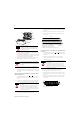
Wiring Connections for the 1794-IP4
Example of 16-bit Period Time Measurement and 16-bit
Accumulating Pulse Counter Wiring (4 channels)
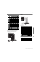
Example of 32-bit Period Time Measurement Wiring
(4 channels)
Input (read) Image
Output/Configuration Image
Channel Signal
Name
1
1794-TB2, -TB3, -TB3S
1794-TBN
2
Signal 0V dc
COM
12...24V
dc
Signal
16-bit Period Time Measurement
0 N A-0 B-17 C-35 B-0
N A-1 B-18 C-36 B-1
1 N A-2 B-19 C-37 B-2
N A-3 B-20 C-38 B-3
2 N A-4 B-21 C-39 B-4
N A-5 B-22 C-40 B-5
3 N A-6 B-23 C-41 B-6
N A-7 B-24 C-42 B-7
32-bit Period Time Measurement
0 D A-8 B-25 C-43 B-8
D A-9 B-26 C-44 B-9
1 D A-10 B-27 C-45 B-10
D A-11 B-28 C-46 B-11
2 D A-12 B-29 C-47 B-12
D A-13 B-30 C-48 B-13
3 D A-14 B-31 C-49 B-14
D A-15 B-32 C-50 B-15
0V dc Terminals 16 thru 33 (1794--TB2, -TB3,
-TB3S)
Terminals
16 and 33
12/24V dc Terminals 34 and 51 (1794-TB2)
Terminals 34 thru 51 (1794-TB3, -TB3S)
Terminals
34 and 51
1 Any unused signals have to be connected to the associated common.
2 Auxiliary terminal blocks are required when using these terminal base units.
N
N
17 18 19 20 21 22 23 24 25 33
012345678
16
35 36 37 38 39 40 41 42
15
51
34
0V dc
12/24V dc
External
Power Supply
12/24V dc
Signal Inputs
Channel 0
Channel 3
Channel 2
Channel 1
0
A
B
C
1
N
N
N
N
N
N
Accumulating Pulse Counter
673452
NOTE: To reduce noise, attach N to 0V dc
Dec. 15 14 13 12 11 10 9 8 7 6 5 4 3 2 1 0
Oct. 17 16 15 14 13 12 11 10 7 6 5 4 3 2 1 0
0 Reserved
1 Counter 00 - 16-bit period measurement for channel 0
2 Counter 01 - pulse counter for channel 0 - 16-bit pulse counting
1 32-bit period measurement for channel 0
2 32-bit period measurement for channel 0
3 Counter 10 - 16-bit period measurement for channel 1
4 Counter 11 - pulse counter for channel 1 - 16-bit pulse counting
3 32-bit period measurement for channel 1
4 32-bit period measurement for channel 1
5 Counter 20 - 16-bit period measurement for channel 2
6 Counter 21 - pulse counter for channel 2 - 16-bit pulse counting
5 32-bit period measurement for channel 2
6 32-bit period measurement for channel 2
7 Counter 30 - 16-bit period measurement for channel 3
8 Counter 31 - pulse counter for channel 3 - 16-bit pulse counting
7 32-bit period measurement for channel 3
8 32-bit period measurement for channel 3
9 Readback of Control Word 2
Reserved R
D
3
R
D
2
R
D
1
R
D
0
M
3
M
2
M
1
M
0
10 Revidion Read - software version code
Where M = Measurement Ready bit - positive edge measurement ready for the respective channel
RD = Reset done
Dec. 15 14 13 12 11 10 9 8 7 6 5 4 3 2 1 0
Oct. 17 16 15 14 13 12 11 10 7 6 5 4 3 2 1 0
0 Control Word 0 - selects the measure function
1 Control Word 1 - sets the clock frequency and period multiple
2 Control Word 2 - sets the start of a new measurement
3 Not used
16
0
34
0V dc
12/24V dc
External
Power Supply
12/24V dc
32-bit period time measurement
Signal Inputs
A
B
C
24 25 26 27 28 29 30 31 32
8 9 10 11 12 13 14 15
42 43 44 45 46 47 48 49 50
33
51
10
11 12 13
D
D
Channel 0
Channel 3
Channel 2
Channel 1
D
D
D
D
D
D
8
9
14 15
NOTE: To reduce noise, attach N to 0V dc