
User guide

3
Publication 1794-IN104A-EN-P - March 2004
Setting the 1794-IM8 Input Filter Time
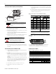
To select your input filter time (FT) for channels 00-07, set the corresponding
bits in the output image table (complementary word) for the module.
Input Filter Time for the 1794-IM8
For example, setting bits 00, 01 and 02 as shown below sets the off-to-on filter
time for inputs 00 thru 07 to 12ms. For other settings, refer to the Input Filter
Time table above.
Specifications
Bits Description
Selected
Filter
Time
Maximum Filter
Time (ms)
02 01 00 Filter Time - inputs 00-07 Off to On On to Off
0 0 0 Filter Time 0 (Default) 256µs 7.5 26.5
0 0 1 Filter Time 1 512µs 8 27
0 1 0 Filter Time 2 1ms 9 28
0 1 1 Filter Time 3 2ms 10 29
1 0 0 Filter Time 4 4ms 12 31
1 0 1 Filter Time 5 8ms 16 35
1 1 0 Filter Time 6 16ms 24.5 44
1 1 1 Filter Time 7 32ms 42 60.5
Specifications 220V ac Input Module, Cat. No. 1794-IM8
Number of Inputs 8, (1 group of 8), nonisolated
Module Location Cat. No. 1794-TBN
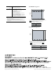
Module Mounting See Derating Curve
On-state Voltage 159V ac minimum
220V ac nominal
264V ac maximum
On-state Current 5.27mA minimum @ 159V ac, 47Hz
9.88mA nominal @ 220V ac, 60Hz
13.21mA maximum @ 264V ac, 63Hz
Off-state Voltage 40V ac maximum
Off-state Current 2.6mA maximum
Input Impedance 22.3K ohms nominal
Nominal Input Current 10mA @ 220V ac, 60Hz
Isolation Voltage Tested at 2600V dc for 1s between user and system
No isolation between individual channels
No isolation between customer power and input channels
Input Filter Time
1
Refer to Input Filter Time table
Flexbus Current 30mA @5V dc
Power Dissipation 4.7W maximum @ 264V ac
Thermal Dissipation Maximum 16.2 BTU/hr @ 264V ac
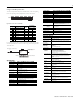
15 14 13 12 11 10 9 8 7 6 5 4 3 2 1 0
FT = 0-07
O:010
Dec.
FLL
I:000
00
Fill File
Source
Destination
Length
#O:010
1
Write FT to complement
of input module.
Write filter time on system startup.
765432 1 0
0
1
0
= 4 Octal or 4 Decimal
1794-IM8
Specifications 220V ac Output Module Cat. No. 1794-OM8
Number of Outputs 8, (1 group of 8), nonisolated
Module Location Cat. No. 1794-TBN, -TBNF
Module Mounting See Derating Curve
Output Current Rating 4.0A (8 outputs @ 500mA)
On-state Current 50mA per output minimum
500mA per output maximum @ 55°C
On-state Voltage Drop maximum 1.5V ac @ 0.5A
Surge Current 7A for 40ms, repeatable every 8s
Off-state leakage 2.5mA maximum
Isolation Voltage Tested at 2600V dc for 1s between user and system
No isolation between individual channels
No isolation between customer power and output channels
Output Signal Delay Time
2
Off to On
On to Off
1/2 cycle maximum
1/2 cycle maximum
Flexbus Current 60mA @5V dc
Power Dissipation 5.0W maximum @ 0.5A
Thermal Dissipation Maximum 17.1 BTU/hr @ 0.5A
Fusing (when using the
1794-TBNF)
3
0.8A, 250 slow-blow fuse
(5 X 20mm SAN-O MQ4-800mA)
General Specifications
Terminal Base Screw
Torque
9 pound-inches (1.0Nm)
Dimensions (with module
installed)
3.7H x 3.7W x 2.7D inches
94H x 94W x 69D mm
Indicators (field side
indication, customer
device driven)
1794-IM8 - 8 yellow status indicators, customer device driven
1794-OM8 - 8 yellow status indicators, logic driven
External ac power
Supply voltage
Input Frequency
Voltage range
220V ac nominal
47-63Hz
159 to 264V ac
Refer to Derating Curves below.
Keyswitch Position 8
Environmental Conditions
Operating
Temperature
IEC 60068-2-1 (Test Ad, Operating Cold),
IEC 60068-2-2 (Test Bd, Operating Dry Heat),
IEC 60068-2-14 (Test Nb, Operating Thermal Shock):
0 to 55°C (32 to 131°F)
Storage Temperature IEC 60068-2-1 (Test Ab, Un-packaged Non-operating Cold),
IEC 60068-2-2 (Test Bb, Un-packaged Non-operating Dry Heat),
IEC 60068-2-14 (Test Na, Un-packaged Non-operating Thermal
Shock):
–40 to 85°C (–40 to 185°F)
Relative Humidity IEC 60068-2-30 (Test Db, Un-packaged Non-operating
Damp Heat):
5 to 95% non-condensing
Vibration IEC60068-2-6 (Test Fc, Operating):
5g @ 10-500Hz
Shock IEC60068-2-27 (Test Ea, Unpackaged shock):
Operating 30g
Non-operating 50g
Emissions CISPR 11:
Group 1, Class A (with appropriate enclosure)
ESD Immunity IEC 61000-4-2:
4kV contact discharges
8kV air discharges
Radiated RF Immunity IEC 61000-4-3:
10V/m with 1kHz sine-wave 80%AM from 30MHz to 1000MHz
10V/m with 200Hz 50% Pulse 100%AM at 900Mhz
EFT/B Immunity IEC 61000-4-4:
±2kV at 5kHz on signal ports
±2kV at 5kHz on power ports
Surge Transient
Immunity
IEC 61000-4-5:
±1kV line-line(DM) and ±2kV line-earth(CM) on signal ports
±1kV line-line(DM) and ±2kV line-earth(CM) on power ports
Conducted RF
Immunity
IEC 61000-4-6:
10Vrms with 1kHz sine-wave 80%AM from 150kHz to 80MHz
Enclosure Type Rating None (open-style)