Installation Instructions FLEX I/O Isolated Input HART Analog Module Catalog Number 1794-IF8IH Topic Page Important User Information 2 Environment and Enclosure 3 Preventing Electrostatic Discharge 4 North American Hazardous Location Approval 5 Install the Module 7 Wire the Module 8 Ground the Module 10 Module Wiring 11 Cyclic HART Input Data 19 Status Indicator 23 Specifications 23 IMPORTANT This module can only be used with 1794-ACN(R)15 with version 5.
FLEX I/O Isolated Input HART Analog Module Important User Information Solid state equipment has operational characteristics differing from those of electromechanical equipment. Safety Guidelines for the Application, Installation and Maintenance of Solid State Controls (Publication SGI-1.1 available from your local Rockwell Automation sales office or online at http://literature.rockwellautomation.
FLEX I/O Isolated Input HART Analog Module 3 Environment and Enclosure ATTENTION This equipment is intended for use in a Pollution Degree 2 industrial environment, in overvoltage Category II applications (as defined in IEC 60664-1), at altitudes up to 2000 m (6562 ft) without derating. This equipment is considered Group 1, Class A industrial equipment according to IEC/CISPR 11.
FLEX I/O Isolated Input HART Analog Module ATTENTION This product is grounded through the DIN rail to chassis ground. Use zinc plated yellow-chromate steel DIN rail to assure proper grounding. The use of other DIN rail materials (for example, aluminum and plastic) that can corrode, oxidize, or are poor conductors, can result in improper or intermittent grounding. Secure DIN rail to mounting surface approximately every 200 mm (7.8 in.) and use end anchors appropriately.
FLEX I/O Isolated Input HART Analog Module 5 North American Hazardous Location Approval The following information applies when operating this equipment in hazardous locations: Informations sur l’utilisation de cet équipement en environnements dangereux: Products marked "CL I, DIV 2, GP A, B, C, D" are suitable for use in Class I Division 2 Groups A, B, C, D, Hazardous Locations and nonhazardous locations only.
FLEX I/O Isolated Input HART Analog Module European Hazardous Location Approval European Zone 2 Certification (The following applies when the product bears the Ex or EEx Marking.
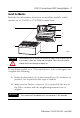
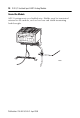
FLEX I/O Isolated Input HART Analog Module 7 Install the Module Read this for information about how to install the module, which mounts on a 1794-TB3 or 1794-TB3S terminal base. 7 3 1 2 6 4 5 44341 ATTENTION During mounting of all devices, be sure that all debris (such as metal chips or wire strands) is kept from falling into the module. Debris that falls into the module could cause damage on power up. To install the module on a 1794 terminal base, refer to the figure and complete the following. 1.
FLEX I/O Isolated Input HART Analog Module 3. Make sure the pins on the bottom of the module are straight so they align properly with the connector in the terminal base. WARNING If you remove or insert the module while the backplane power is on, an electrical arc can occur. This could cause an explosion in hazardous location installations. Be sure that power is removed or the area is nonhazardous before proceeding. 4.
FLEX I/O Isolated Input HART Analog Module 9 3. Connect the +V DC power lead to terminal 34 on the 34…51 row C, and the -V common/return to terminal 16 on the 16…33 row B. ATTENTION To reduce susceptibility to noise, power analog modules and digital modules from separate power supplies. Do not exceed a length of 3 m (9.8 ft) for DC power cabling. 4. If daisy-chaining power to the next terminal base, connect a jumper from terminal 51 (+V DC) on this base unit to terminal 34 on the next base unit. 5.
FLEX I/O Isolated Input HART Analog Module Ground the Module All I/O wiring must use shielded wire. Shields must be terminated external to the module, such as bus bars and shield-terminating feed-throughs.
FLEX I/O Isolated Input HART Analog Module 11 Module Wiring 0 1 2 3 4 5 6 7 8 9 10 11 12 13 14 15 16 17 18 19 20 21 22 23 24 25 26 27 28 29 30 31 32 33 34 35 36 37 38 39 40 41 42 43 44 45 46 47 48 49 50 51 Row A Row B Row C Label placed at top of wiring area Row A Row B Row C Current Input Current Input AC or DC Four-wire Current Transmitter DC only Three-wire Current Transmitter Current Input 1794-TB3S shown 44319 DC only Two-wire Current Transmitter Publication 1794-IN115C-EN-P - April 2009
FLEX I/O Isolated Input HART Analog Module Wire Connections Channel Signal Type Label Markings Catalog Numbers 1794-TB3 or 1794-TB3S Terminal 0 Current I0 A-0 Current I0 Ret A-1 Current I1 A-2 Current I1 Ret A-3 Current I2 A-4 Current I2 Ret A-5 Current I3 A-6 Current I3 Ret A-7 Current I4 A-8 Current I4 Ret A-9 Current I5 A-10 Current I5 Ret A-11 Current I6 A-12 Current I6 Ret A-13 Current I7 A-14 Current I7 Ret A-15 1 2 3 4 5 6 7 -V DC common
FLEX I/O Isolated Input HART Analog Module 13 Input Map Word Bit 15 14 13 12 11 10 9 8 7 6 5 4 3 2 1 0 0 Channel 0 Input Data 1 Channel 1 Input Data 2 Channel 2 Input Data 3 Channel 3 Input Data 4 Channel 4 Input Data 5 Channel 5 Input Data 6 Channel 6 Input Data 7 Channel 7 Input Data 8 H 7 H 6 H 5 H 4 H 3 H 2 H 1 H 0 L 7 L 6 L 5 L 4 L 3 L 2 L 1 L 0 9 R 7 R 6 R 5 R 4 R 3 R 2 R 1 R 0 P 7 P 6 P 5 P 4 P 3 P 2 P 1 P 0 10 Reserved 11 C 7 C 6
FLEX I/O Isolated Input HART Analog Module Configuration Map Word Bit 15 14 13 12 11 10 9 8 7 6 5 4 3 2 1 0 R R F7 F6 F5 F4 BOB(1) R R F3 F2 F1 F0 BOA(1) 1 D H 7 D H 6 D H 5 D H 4 D H 3 D H 2 D H 1 2 CH 3 Format CH 2 Format CH 1 Format CH 0 Format 3 CH 7 Format CH 6 Format CH 5 Format CH 4 Format 4 CH1 HART Current Ratio FLTR1 CH0 HART Current Ratio FLTR0 5 CH3 HART Current Ratio FLTR3 CH2 HART Current Ratio FLTR2 6 CH5 HART Current Ratio FLTR5
FLEX I/O Isolated Input HART Analog Module 15 Configuration Map Word Bit 15 14 13 12 11 10 29… 32 Words 9…12 for channel 5 33… 36 Words 9…12 for channel 6 37… 40 Words 9…12 for channel 7 41 Reserved 9 8 7 6 5 4 3 2 1 0 C 7 C 6 C 5 C 4 C 3 C 2 C 1 C 0 Note: Reserved data may not be shown in certain controller software (1) not shown or used in RSLogix 5000.
FLEX I/O Isolated Input HART Analog Module Configuration Map descriptions Cn HART CMD 3 Disable 0: HART CMD 3 communications enabled R Reserved CH N Format Refer to the Channel Data Formats table 1: HART CMD 3 communications disabled Byte Order Byte Order Group B Byte Order Group A Bit 9 Bit 8 Bit 1 Bit 0 Description 0 0 0 0 Little Endian Format (default) — all data entries in true Little Endian format 1 0 1 0 Word Swap — word swap only values requiring more than one word, for exa
FLEX I/O Isolated Input HART Analog Module 17 Channel Digital Filter Digital Filter frequency Decimal Value Bits 10 9 8 2 1 0 4.
FLEX I/O Isolated Input HART Analog Module Channel Data Formats Format Bits (1) 15 11 7 3 14 10 6 2 13 9 5 1 12 8 4 0 Format Name Signal Range User Range LO HI LO Resolution HI 0 0 0 0 0 0…20 mA in 0.00 Milliamps 22.00 0 22000 1.0 µA (0.000 mA) (22.000 mA) 1 0 0 0 1 0…20 mA in 0.00 % Full Scale 22.00 0 (0%) 11000 (110.00%) 2.0 µA 3 0 0 1 1 0…20 mA in 0.00 UINT 20.00 0 65535 0.3052 µA 4(2) 0 1 0 0 4…20 mA in 2.00 Milliamps 22.00 2000 22000 1.0 µA (2.000 mA) (22.
FLEX I/O Isolated Input HART Analog Module 19 Format Values Format Format name 0.0 mA 2.0 mA 4.0 mA 20.0 mA 22.
FLEX I/O Isolated Input HART Analog Module HART Input Data Word Bit 15 14 13 12 11 10 9 8 7 6 5 4 3 2 1 0 C H 7 C H 6 C H 5 C H 4 C H 3 C H 2 C H 1 C H 0 0 Reserved 1 Reserved 2 CH0 HART Field Device Status 3 Reserved 4 CH0 HART Primary Value (IEEE 754-1985 Single-Precision 32 bit floating point) (HART CMD 3 Communications Status) F V A T V A CH0 HART Comm Status S V A P V A CH0 HART Loop Status 5 6 CH0 HART Secondary Value (IEEE 754-1985 Single-Precision 32 bit
FLEX I/O Isolated Input HART Analog Module 21 HART Input Data Word Bit 15 14 13 12 11 10 50… 61 Words 2…13 for channel 4 62… 73 Words 2…13 for channel 5 74… 85 Words 2…13 for channel 6 86… 97 Words 2…13 for channel 7 9 8 7 6 5 4 3 2 1 0 Publication 1794-IN115C-EN-P - April 2009
FLEX I/O Isolated Input HART Analog Module HART Input Data descriptions CHn: HART CMD 3 Communication Status 0: HART CMD3 Communication Disabled or No Error CHn: HART Comm Status (HART CMD3 Response first status byte): Refer to User Manual CHn: HART Field Device Status (HART CMD3 Response second status byte): Refer to User Manual Chn: HART Loop Status: Bit 0: HART enable Bit 1: Device Connected Bit 2: Response Error Bit 3: CMD 48 Update Bit 4: HART Loop Tolerance Error Bit 5: HART Update Bit 6: HA
FLEX I/O Isolated Input HART Analog Module 23 Status Indicator The OK status indicator is bicolor, red, and green. The indicator flashes green for these reasons: • The module configuration word is zero (for example, powerup reset condition). • The 24V DC user power is off. • The module is in Configuration mode. The indicator displays red to indicate the module did not pass the initial hardware test. Recycle power in response to this display.
FLEX I/O Isolated Input HART Analog Module FLEX I/O 8-input Isolated HART Module - 1794-IF8IH Attribute Value Normal mode rejection ratio - current terminal >70 dB @ 50/60 Hz (4.17 Hz ADC conversion rate) >65 dB @ 50/60 Hz (10.0 Hz ADC conversion rate) >75 dB @ 50 Hz (16.7 Hz ADC conversion rate) >85 dB @ 60 Hz (19.6 Hz ADC conversion rate) Common mode rejection ratio >60 dB at 50 Hz >60 dB at 60 Hz Step response to 99% current terminal 4.17 Hz conversion rate = 480 ms 10.
FLEX I/O Isolated Input HART Analog Module 25 FLEX I/O 8-input Isolated HART Module - 1794-IF8IH Attribute Value Wiring category(3) 2 on signal ports 3 on power ports Wire type Shielded on signal ports Flexbus current 80 mA Thermal dissipation, max 6.8 BTU/hr @31.2V DC Keyswitch position 3 External DC power supply voltage 24V DC nom External DC power supply voltage range 19.2…31.2V DC (includes 5% AC ripple) External DC power supply current 190 mA @ 24V DC Dimensions (HxWxD), approx. 94.
FLEX I/O Isolated Input HART Analog Module Environmental Attribute Value Temperature, operating IEC 60068-2-1 (Test Ad, Operating Cold), IEC 60068-2-2 (Test Bd, Operating Dry Heat), IEC 60068-2-14 (Test Nb, Operating Thermal Shock): 0…55 °C (32…131 °F) Temperature, nonoperating IEC 60068-2-1 (Test Ab, Unpackaged Nonoperating Cold), IEC 60068-2-2 (Test Bb, Unpackaged Nonoperating Dry Heat) IEC 60068-2-14 (Test Na, Unpackaged Nonoperating Thermal Shock): –40…85 °C (–40…185 °F) Relative humidity IEC
FLEX I/O Isolated Input HART Analog Module 27 Environmental Attribute Value EFT/B Immunity IEC 61000-4-4: ±3 kV at 5 kHz on signal ports Surge Transient Immunity IEC 61000-4-5: ±2 kV line-earth(CM) on shielded ports Conducted RF Immunity IEC 61000-4-6: 10V rms with 1 kHz sine-wave 80%AM from 150 kHz…80 MHz Certifications Certification (when Value product is marked)(1) c-UL-us UL Listed Industrial Control Equipment, certified for US and Canada. See UL File E65584.
Rockwell Automation Support Rockwell Automation provides technical information on the Web to assist you in using its products. At http://support.rockwellautomation.com, you can find technical manuals, a knowledge base of FAQs, technical and application notes, sample code and links to software service packs, and a MySupport feature that you can customize to make the best use of these tools.