
Instruction Manual

Publication 1794-6.5.8 - January 2010
Communication and I/O Image Table Mapping with the DeviceNet/ControlNet Adapter 81
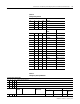
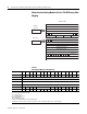
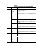
Table 5.4
Setting the Input Filter
Bits Channel
03 02 01 00 Input 0
07 06 05 04 Input 1
11 10 09 08 Input 2
15 14 13 12 Input 3
A/D Conversion
Rate
Low Pass Filter
0 0 0 0 1200Hz No low pass
0 0 0 1 1200Hz 100ms low pass
0 0 1 0 1200Hz 500ms low pass
0 0 1 1 1200Hz 1000ms low pass
0 1 0 0 600Hz No low pass
0 1 0 1 600Hz 100ms low pass
0 1 1 0 600Hz 500ms low pass
0 1 1 1 600Hz 1000ms low pass
1 0 0 0 300Hz No low pass
1 0 0 1 300Hz 100ms low pass
1 0 1 0 300Hz 500ms low pass
1 0 1 1 300Hz 1000ms low pass
1 1 0 0 150Hz No low pass
1 1 0 1 150Hz 100ms low pass
1 1 1 0 150Hz 500ms low pass
1 1 1 1 150Hz 1000ms low pass
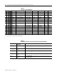
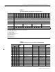
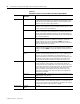
Table 5.5
Configuring Your Input Module
Input Channel Configuration
03 02 01 00 Set these bits for Channel 0
07 06 05 04 Set these bits for Channel 1
11 10 09 08 Set these bits for Channel 2
15 14 13 12 Set these bits for Channel 3
Bit Settings Input
Values
Data Format % Underrange
%Overrange
Input Range
(2)
Module Update Rate
Hexadecimal Decimal (RTSI = 0) (RTSI = 0)
IT = 1
0 0 0 0 Channel not configured