
Instruction Manual

Publication 1794-6.5.8 - January 2010
How to Install Your Analog Module 29
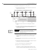
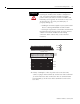
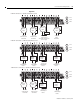
Figure 2.6
1794-IF4I
Connections ± 1794-TB3 terminal base shown
+
3-Wire Current
Transmitter
dc only
2-Wire Current
Transmitter and External
Power Supply
Current only
+
+
±±
3-Wire
Transmitter
dc only
±±
Voltage
Input
I I I I
+
±
0 ±15
34±51
16±33
A
B
C
+±
+±
ac or dc
4-Wire Current
Transmitter
+
Current
Input
Current
Input
Current
Input
+
dc only
Current only
+
+
dc only
I
+
±
0 ±15
34±51
16±33
A
B
C
+±
+±
ac or dc
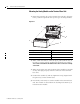
4-Wire Output
Device
+
1794-OF4I
Connections ± 1794-TB3 terminal base shown
±±
Current
Output
Device
Current
Output
Device
Current
Output
Device
Voltage
Output
Device
I I
3-Wire Output
Device
2-Wire Output
Device
3-Wire Output
Device
I
±
24V
dc
Power Supply
+
±
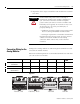
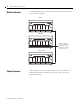
1794-IF2XOF2I
Connections ± 1794-TB3 terminal base shown
+
3-Wire Current
Transmitter
dc only
±±
I I
0 ±15
34±51
16±33
A
B
C
+±
+±
ac or dc
4-Wire Current
Transmitter
+
Current
Input
Current
Input
+
+
Voltage
Output
Device
I
±
dc only
3-Wire Output
Device
Current only
+
±
Current
Output
Device
2-Wire Output
Device
I