
Instruction Manual

Publication 1794-6.5.8 - January 2010
104 Input, Output, Status and Configuration Files for Analog Modules when used with ControlNet
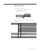
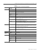
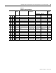
Table 6.2 Output (Configuration) Map
Dec. 15 14 13 12 11 10 9 8 7 6 5 4 3 2 1 0
Oct. 17 16 15 14 13 12 11 10 7 6 5 4 3 2 1 0
Word 0 EN 0 0 0 0 0 0 0 0 0 0 0 0 0 0 0
Word 1 Channel 3 Filter Channel 2 Filter Channel 1 Filter Channel 0 Filter
Word 2 Ch 3 Configuration Ch 2 Configuration Ch 1 Configuration Ch 0 Configuration
Word 3 0 Real Time Sample Interval
Word 4 IC 1 TR IT 0 CH SK FS RV QK CK GO Channel Number
Word 5 Reserved
Where :
EN = Enable bit (not used on input module)
IC = Initiate Configuration bit
TR = Transparent bit
IT = Interrupt toggle bit
CH - Chop Mode Disable.
SK = FIR Filter Disable
FS = Fast Step Response
RV = Revert to default bit
QK = Quick calibration
CK = Calibration clock
GO = Gain Offset select
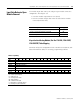
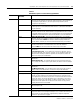
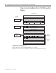
Table 6.3
Word/Bit Descriptions for Isolated Analog Input Module
Word Decimal Bit
(Octal Bit)
Definition
Input Word 0 Bits 00-15
(00-17)
Channel 0 analog data – Real time input data per your configuration
Word 1 Bits 00-15
(00-17)
Channel 1 analog data – Real time input data per your configuration
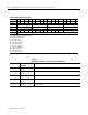
Word 2 Bits 00-15
(00-17)
Channel 2 analog data – Real time input data per your configuration
Word 3 Bits 00-15
(00-17)
Channel 3 analog data – Real time input data per your configuration
Word 4 Bits 00-15
(00-17)
Real Time Sample. The elapsed time in increments programmed by the real time
sample interval.