' " & !%$ " $ " % $ ' " #
Important User Information Because of the variety of uses for the products described in this publication, those responsible for the application and use of this control equipment must satisfy themselves that all necessary steps have been taken to assure that each application and use meets all performance and safety requirements, including any applicable laws, regulations, codes and standards. The illustrations, charts, sample programs and layout examples shown in this guide are intended solely for example.
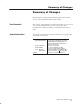
The information contained in this manual pertains to the series B version of the 1794-ID2 frequency input module. New Information Updated Information This version of this publication contains information on control word 2, for setting the filter function for the counters. This filter information is contained in chapter 1 and identified in chapters 4 and 5. The vibration specifications for this module have been updated. The specification is as follows: 07,310/(05$.
soc–ii Summary of Changes
Preface Using This Manual Purpose of this Manual Audience This manual shows you how to use your FLEX I/O pulse counter module with Allen-Bradley programmable controllers. The manual helps you install, program and troubleshoot your module. You must be able to program and operate an Allen-Bradley programmable controller to make efficient use of your FLEX I/O module. In particular, you must know how to program block transfers. We assume that you know how to do this in this manual.
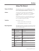
P–2 Using This Manual Appendix A Title .$"(%(" 1(-,0 Conventions Contents .$"(%(" 1(-,0 %-/ 1'$ .2*0$ "-2,1$/ +-#2*$ We use these conventions in this manual: In this manual, we show: Like this: 1' 1 1'$/$ (0 +-/$ (,%-/+ 1(-, !-21 1-.(" (, ,-1'$/ "' .1$/ (, 1'(0 + ,2 * 1' 1 1'$/$ (0 +-/$ (,%-/+ 1(-, !-21 1'$ 1-.
Using This Manual Catalog Number Voltage 9 # " '& 9 Publications Description Installation Instructions User Manual .054 54054 .$,/) /'5,( 9 9 " '& 54054 3/,$4(' .$,/) /'5,( 9 9 " '& .054 3/,$4(' .$,/) /'5,( 9 9 # " '& .054 54054 3/,$4(' .$,/) /'5,( 9 9 " '& .054 .$,/) /'5,( 9 9 9 " '& *(2-/&/50,( .
P–4 Using This Manual
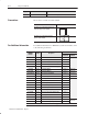
Table of Contents Overview of the Incremental Encoder Module Chapter 1 How to Install Your Incremental Encoder Module Chapter 2 $-&7 !-.6 -&37*5 217&.16 2: %28 "6* 7-* 1(5*0*17&/ 1(2)*5 2)8/* $-&7 7-* 1(5*0*17&/ 1(2)*5 2)8/* 2*6 !<3.(&/ 33/.(&7.216 1387 &3&'./.7.
ii Table of Contents Programming Your Incremental Encoder Module Chapter 3 Writing Configuration to and Reading Status from Your Module with a Remote I/O Adapter Chapter 4 How Communication Takes Place and I/O Image Table Mapping with the DeviceNet Adapter Chapter 5 4#,*$"3*/. 8 "7 )"3 )*2 )"03&1 /.3"*.2 .3&1 ,/$+ 1".2'&1 .2314$3*/.
iii Table of Contents Input, Output and Configuration Files for Analog Modules when used with ControlNet Chapter 6 *#25'3 $,'%5+7'4 $165 5*' 10531. '5 �'3 %*'&6.'& #5#: 3#04('3 04%*'&6.'& #5#: 3#04('3 1&6.
Table of Contents
Overview of the Incremental Encoder Module What This Chapter Contains How You Use the incremental encoder Module Read this chapter to familiarize yourself with the 1794–ID2 module.
1–2 Overview of the Incremental Encoder Module %($ $)%" &' & ' ( !'( & ! # " !'( & + & ' ( !'( & Z+ Z- $ ! ( !'( & A+ A- + $)#( & !'( & B+ BZ+ ZG+ G- $#(&$" $& Internal +5V dc What the Incremental Encoder Module Does B+ B- G+ G- $#(&$" $& ! # " !'( & )' #( & &! " )' ( !'( & $ ! $)#( & !'( & A+ A- * #! ""+ '$" ( $#* &( & 12-24V dc 0V The incremental encoder module performs high-speed scaling calculation operations for
Overview of the Incremental Encoder Module !-* &)&37*5 75&16+*56 <285 (21+.,85&7.21 )&7& 72 7-* 02)8/* 86.1, & !$ 1–3 ;7*51&/ )*9.(*6 75&160.7 +5*48*1(< 6.,1&/6 72 7-* 02)8/* /*;'86 ! 1 ! ! # " ! " ! # $ " % ! = %285 /&))*5 352,5&0 .16758(76 7-* &)&37*5 72 3*5+250 & ! 2+ 7-* 9&/8*6 &1) 6725*6 7-*0 .1 & )&7& 7&'/* !-* 02)8/* (219*576 +5*48*1(< 6.,1&/6 .172 .
1–4 Overview of the Incremental Encoder Module How the incremental encoder Operates The counter module handles up/down counting and detection of selectable number of edges (X1, X2, X4) for incremental encoders with 2 pulse trains, nominal 90o out of phase. The minimum stable input condition is 2µs.The following paragraphs detail operation of the incremental encoder module. Each of the 2 counters has a 16–bit counter register, a preset register and a latch register.
Overview of the Incremental Encoder Module 1–5 Up/Down Counting Controlled by B Input Pulse Counting (Mode 000) Up/Down counting controlled by input B %$'!(!* $ ( %)"' ' & $)#( ( !#%)( !#%)( ( $)#( & $)#(' )% ! ( $)#( & $)#(' $+# Counter Mode = 0 Logic Counter Register A % $+# B = 0/1 Input A Input B 0 Counter Value 1 2 Counting Up 3 2 1 Counting Down Up/Down Counting using Pulses at Inputs A and B Pulse Counting Mode (100) Up/Down Counting
1–6 Overview of the Incremental Encoder Module Count Pulses from Incremental Encoders Up/Down Counting using pulses at the inputs of A and B Pulse Counting Mode (001, 010. 011) ',&+ )%' ') +" & ') ! * ' +" (,$* +) #& -#$$ ',&+ " ',&+ #) +#'& ,( '-& #* + )%#& .
Overview of the Incremental Encoder Module 1–7 Preset Function Use the preset function to copy a value from the preset register to the counter register. Method 1 +","- "$&,-"+ ).(-"+ "$&,-"+ Method 2 +","- "$&,-"+ )$& ).(-"+ "$&,-"+ The flag PresetReached is set when the counter register and the preset register are equal (if the counter preset is reached, or if the counter has been loaded with the preset value).
1–8 Overview of the Incremental Encoder Module Store Function Use the store function to copy the value in the counter register (Counter) to the latch register (StoreValue). The StoreControl parameter determines the store function. Execution occurs on either the positive or negative edge of input signals G and Z respectively (see table). The parameter is a 2–bit binary code in write word 1 (bits 11 and 12) ') ') $+* $& ).
Overview of the Incremental Encoder Module 1–9 Count Up pulse (+) %- (!# (-', * * + , %- (-', * !#+, * Count Down pulse (-) * + , !#+, * (-', * (!# (-', * !#+, * Note: ," )* + , * !#+, * . %- ," (-', * * , #'+ ," . %- Filter Function The filter function is only valid during mode 000 (pulse counting). You enable the filter function by setting bits in Control word 2.
1–10 Overview of the Incremental Encoder Module Chapter Summary In this chapter, you learned about the incremental encoder module, block transfer communication, and details of how the module functions. Now you can install the module.
How to Install Your Incremental Encoder Module What This Chapter Contains Before You Install Your Input Module In this chapter, we tell you about: For information on See page !"*-! *0 )./ '' *0- * 0'! 0-*+! ) )%*) %-! /%1!. *2!- !,0%-!(!)/. ).
2–2 How to Install Your Incremental Encoder Module Low Voltage Directive This product is tested to meet Council Directive 73/23/EEC Low Voltage, by applying the safety requirements of EN 61131–2 Programmable Controllers, Part 2 – Equipment Requirements and Tests. For specific information required by EN 61131-2, see the appropriate sections in this publication, as well as Allen-Bradley publication 1770-4.1, Industrial Automation Wiring and Grounding Guidelines.
How to Install Your Incremental Encoder Module 2–3 Methods of wiring the terminal base units are shown in the illustration below. Wiring the Terminal Base Units (1794ĆTB3G shown) ! ATTENTION: Do not daisy chain power or ground from the terminal base unit to any ac or dc digital module terminal base unit. DaisyĆchaining $' + & '- % ' ( + ( .% $' + & '- % ' ( + ( .% & ( .% $' + & '- % ' ( + ( .% Note: %% &( .% , &.,- ).%, !+ *. ' 0 (+ & &( .% , !(+ -#$, ('!$".
2–4 How to Install Your Incremental Encoder Module Installing the Module Installation of the incremental encoder module consists of: • mounting the terminal base unit • installing the module into the terminal base unit • installing the connecting wiring to the terminal base unit If you are installing your module into a terminal base unit that is already installed, proceed to “Mounting the incremental encoder Module on the Terminal Base” on page 2–7.
How to Install Your Incremental Encoder Module 2–5 & & $ ! % '! & "( $ & & !%& & #& $ %'$ & "" "! & & $ ! % % % '! $ & " & #& $ ! & * '% "!! &"$ % ' + $ &$ & $ %% ")! "! & & $ ! % '! & &" " & & $ ! % "! & $ & & $ ! % " % !"& " !&" # '% % $ ) $ ( $ "$ % $ ( &" "# ! & " ! & #$ %% ")! "! & & $ ! % '!& '% ) & & $ ! $ % & " ! &
2–6 How to Install Your Incremental Encoder Module 5. Repeat the above steps to install the next terminal base.
How to Install Your Incremental Encoder Module 2–7 Drilling Dimensions for Panel/Wall Mounting of FLEX I/O Inches (Millimeters) 2. Drill the necessary holes for the #6 self-tapping mounting screws. 3. Mount the mounting plate (1) for the adapter module using two #6 self-tapping screws (18 included for mounting up to 8 modules and the adapter). Important: More Make certain that the mounting plate is properly grounded to the panel.
2–8 How to Install Your Incremental Encoder Module 2. Make certain the flexbus connector (3) is pushed all the way to the left to connect with the neighboring terminal base/adapter. You cannot install the module unless the connector is fully extended. 3. Make sure that the pins on the bottom of the module are straight so they will align properly with the connector in the terminal base unit. ! ATTENTION: Remove field-side power before removing or inserting the module.
How to Install Your Incremental Encoder Module Connecting Wiring for Your incremental encoder Module 2–9 Wiring to the module is made through the terminal base unit on which the module mounts.
2–10 How to Install Your Incremental Encoder Module 3. Terminate shields to terminals 16 or 33 on row B, or 40 through 45 on row C. 4. Connect +24V dc to terminal 34 on the 34-51 row (C). 5. Connect dc return to terminal 16 on the 16–33 row (B). ! ATTENTION: To reduce susceptibility to noise, power frequency modules and digital modules from separate power supplies. Do not exceed a length of 33 ft (10m) for dc power cabling. 6.
How to Install Your Incremental Encoder Module 2–11 Wiring to a 1794ĆTBN or ĆTBNF Terminal Base Unit 1. Connect individual input wiring (A+, A–, B+, B–, Z+, Z–, G+, G–) to the even numbered terminals on row (B) as indicated in the table below. ATTENTION: Do not connect maximum input voltage simultaneously to all inputs if the module ambient temperature is expected to exceed 40oC.
2–12 How to Install Your Incremental Encoder Module Wiring connections for the 1794-ID2 incremental encoder Module Terminal Base Units 1794-TB3, -TB3S Signal 0V dc Terminal Base Units 1794-TBN, -TBNF1 12/24V dc Signal Input '+".$*$+0 ) $+",#$. & ++$) '+".$*$+0 ) $+",#$. & ++$) #" #" $.*'+ )/ +# $.*'+ )/ 0&.
How to Install Your Incremental Encoder Module 2–13 Example of Pulse Transmitter Wiring incremental encoder Channel 0 #!& $ ') ',&+ ) ! + G + #!& $ ') ',&+ ) $# ) 0 +#'& () * + Z + B + #!& $ ') ,( '-& ',&+#&! A + #!& $ &(,+* .+ )& $ '- ) ,(($/ .
2–14 How to Install Your Incremental Encoder Module Module Indicators The incremental encoder module has one status indicator (PWR) that is on when power is applied to the module, and one input status indicator for each input (12 in all). 1794-ID2 2 CH INCREMENTAL ENCODER MODULE A B Z G + - C A B Z 1 G B + - A A = Power/status indicator – indicates power applied to module and status of module. B = Insertable label for writing individual I/O assignments.
Programming Your Incremental Encoder Module What This Chapter Contains To initiate communication between the incremental encoder module and your PLC processor, you must enter block transfer instructions into your ladder logic program. Use this chapter to enter the necessary block transfer instructions into your ladder logic program.
3–2 Programming Your Incremental Encoder Module PLCĆ2 Family Processor The 1794 incremental encoder module is not recommended for use with PLC-2 family programmable controllers due to the number of digits needed for high resolution. Important: The incremental encoder module functions with reduced performance in PLC-2 systems.
Programming Your Incremental Encoder Module 8 1/$&22/1 1/(1"- 6"-0,& 3–3 4.( )& -/%4,& *2 ,/$"3&% *. 1"$+ (1/40 2,/3 )& *.3&(&1 $/.31/, '*,& 23"132 "3 )& %"3" 2&.3 #7 3)& 8 01/$&22/1 3/ 3)& -/%4,& 23"132 "3 ".% *2 5/1%2 ,/.( 3 0/5&1 40 *. -/%& /1 5)&. 3)& 01/$&22/1 *2 '*123 25*3$)&% '1/- 3/ 3)& 42&1 01/(1"- &."#,&2 " #,/$+ 31".2'&1 51*3& 3/ $/.'*(41& 3)& -/%4,& *123 2$". /' ,"%%&1 /1 ! /.
3–4 Programming Your Incremental Encoder Module Figure 3.1SLC Programming for the 1794ĆOF4I Isolated Analog Output Module Program Action 0000 39*5"4 .7 !-.6 582, (32+.,85*6 7-* '03(/ 75&26+*5 34*5&7.32 7;4* 0*2,7- &2) &))5*66 &7 439*5<84 .7 1867 '* 6*7 73 73 .2).(&7* & ! &2) '.7 1867 '* 73 .2).(&7* & !# ! % ! $ " ! ! !#% ! $ " ! ! 0001 ! 67&786 .6 (34.*) 73 7-* &5*& 9-*2 & ! .6 .
Programming Your Incremental Encoder Module 3–5 Program Action 0005 #! # &/,3 ( #! 79**,77-911< *4251,8,7 (3+ 8/, +43, )08 07 +,8,*8,+ 8/, #! +(8( 07 *450,+ 0384 8/, 84 (6,( ' " $! "# # #! $ #! # $ #! "# #$" &/, ( #! ,6646 4**967 8/, ,6646 *4+, 07 24:,+ 84 0006 #! !! ! # % % " $! "# #! $ #! # $ #
3–6 Programming Your Incremental Encoder Module Program Action When a BTW occurs, the error code is moved to N7:17. 0008 BTW ERROR BIT B3:10 MOV MOVE SOURCE 12 #M1:1.203 6 #N7:17 0< DEST BTW PENDING B3:15 U 0 BTW ENABLE BIT B3:110 U 15 CHECK BTW STATUS B3:15 L 1 0009 BTR ENABLE BIT B3:100 BTR DONE BIT B3:0 15 This rung executes BTRs continuously, as fast as possible. BTR ERROR BIT B3:0 13 12 BTR PENDING B3:5 L 0 BTR ENABLE BIT B3:100 L 15 0010 One BTW is triggered at power up.
Programming Your Incremental Encoder Module 3–7 Program Action 0011 ()0 #-,1/-* 4-/$ )0 +-3%$ 1- 1(% &)*% &-/ 1(% 0#!,,%/ +-$2*% 4()*% 1(% )0 ), ./-'/%00 2,1)* 1(% %,!"*% $-,% !,$ %//-/ ")10 !/% 12/,%$ -&& 0012 ()0 #-,1/-* 4-/$ )0 +-3%$ 1- 1(% &)*% &-/ 1(% 0#!,,%/ +-$2*% 4()*% 1(% )0 ), .
3–8 Programming Your Incremental Encoder Module Chapter Summary In this chapter, you learned how to program your ID2 incremental encoder module using block transfer instructions and ladder logic. Now, you can configure your module.
Writing Configuration to and Reading Status from Your Module with a Remote I/O Adapter What This Chapter Contains In this chapter, we tell you about: For information on See page *)"%#/,%)# */, * /'! ! %)# . ",*( */, * /'! ++%)# . "*, .$! * /'! ) ,!(!). ' ) * !, * /'! 1 ( #! '! ++%)# '* & , )-"!, ! *, --%#)(!).
4–2 Writing Configuration to and Reading Status from Your Module with a Remote I/O Adapter During normal operation, the processor transfers from 1 to 4 words to the module when you program a BTW instruction to the module’s address. Reading Data From Your Module Mapping Data for the Module Read programming moves status and data from the frequency input module to the processor’s data table in one I/O scan.
Writing Configuration to and Reading Status from Your Module with a Remote I/O Adapter 4–3 Block Transfer Read Word Assignments for the Incremental Encoder Module (1794-ID2) (Octal Bit⇒) 17 16 15 14 13 12 11 10 07 06 05 04 03 02 01 00 Dec.
4–4 Writing Configuration to and Reading Status from Your Module with a Remote I/O Adapter Read Word !03& %0/5+/6'& Bit Definition +5 Status for input Z 16-4' 53#/4.+55'3 *+4 $+5 8*'/ 4'5 +/&+%#5'4 # 4+)/#- #5 " +5 Status for input G 16-4' 53#/4.
Writing Configuration to and Reading Status from Your Module with a Remote I/O Adapter 4–5 Block Transfer Write Word Assignments for the Incremental Encoder Module (Octal Bit) ⇒ 17 16 15 14 13 12 11 10 07 06 05 04 03 02 01 00 Dec. Bit ⇒ 15 14 13 12 11 10 09 08 07 06 05 04 03 02 01 00 Word⇓ Write .'33+1 438641 $46* !+87 8.+ ,93)8/43 4, )4938+6 .'33+1 438641 $46* !+87 8.+ ,93)8/43 4, )4938+6 .'33+1 6+7+8 :'19+ 84 14'* 46 )425'6+ ;/8. )4938+6 .
4–6 Writing Configuration to and Reading Status from Your Module with a Remote I/O Adapter Write Word Bit "3-5) "13( '105-06)( -54 Definition Store Control bits - ,)4) &-54 8-.. 53-++)3 % 513) 10.: -* 5,) ',%00). 513) 45%564 &-5 13 -4 '.)%3)( %7) 5,) '1605)3 7%.6) 10 5,) 214-5-7) )(+) 1* $ -* 513)( # %7) 5,) '1605)3 7%.6) 10 5,) 214-5-7) )(+) 1* -* 513)( # %7) 5,) '1605)3 7%.6) 10 5,) 0)+%5-7) )(+) 1* -* 513)( # %7) 5,) '1605)3 7%.
Writing Configuration to and Reading Status from Your Module with a Remote I/O Adapter Write Word Bit %57+ *54904:,+ 098 4–7 Definition Calibration Control bits - )098 (4+ Enable bit - %/,4 9/08 )09 08 8,9 9/, *5:49,7 *(4 ), *(20)7(9,+ Direction bit - %/,4 9/08 )09 8,9 *(20)7(9054 08 6,7-573,+ 04 ( 4,.(90;, +07,*9054
4–8 Writing Configuration to and Reading Status from Your Module with a Remote I/O Adapter
How Communication Takes Place and I/O Image Table Mapping with the DeviceNet Adapter What This Chapter Contains In this chapter, we tell you about: For information on See page */. !0% ! !. ) #!, *".1 ,! *''! .,/ ./,! +.!, )+/. . ./- *, 2-.!( $,*/#$+/.
5–2 How Communication Takes Place and I/O Image Table Mapping with the DeviceNet Adapter Adapter Input Status Word The input status word consists of: • I/O module fault bits – 1 status bit for each slot • node address changed – 1 bit • I/O status – 1 bit *#/($ /(. '. (*. (*. (*. *. -$# (*. (*. (*. .&,*/%& (*. (*. '. . .$ '. *#$ ##,$-- & )%$# '. The adapter input status word bit descriptions are shown in the following table.
How Communication Takes Place and I/O Image Table Mapping with the DeviceNet Adapter System Throughput 5–3 System throughput, from incremental encoder to backplane, is a function of: • the configured minimum frequency sample time • the number of channels actually configured for connection to a specific sensor (0 or 1) You can set the minimum frequency time during module configuration. The selection influences the sample data rate, thus affecting system throughput.
5–4 How Communication Takes Place and I/O Image Table Mapping with the DeviceNet Adapter Block Transfer Read Word Assignments for the Incremental Encoder Module (1794-ID2) (Octal Bit⇒) 17 16 15 14 13 12 11 10 07 06 05 04 03 02 01 00 Dec. Bit ⇒ 15 14 13 12 11 10 09 08 07 06 05 04 03 02 01 00 Word⇓ Read .2 31%$ (!--%+ 2.0%$ #.3-2%0 4!+3% .- #(!--%+ (!--%+ 2.0%$ #.3-2%0 4!+3% .
How Communication Takes Place and I/O Image Table Mapping with the DeviceNet Adapter 5–5 Bit/Word Definitions for the incremental encoder Module (1794-ID2) Word Bit Definition # " ,/" '1 Status for input A -2)0# 1/ +0*'11#/ &'0 '1 4&#+ 0#1 '+"'! 1#0 0'%+ ) 1 '1 Status for input B -2)0# 1/ +0*'11#/ &'0 '1 4&#+ 0#1 '+"'! 1#0 0'%+ ) 1 '1 Status for input Z -2)0# 1/ +0*'11#/ &'0 '1 4&#+ 0#1 '+"'! 1#0 0'%+ ) 1 '1 Status for input G -2)0
5–6 How Communication Takes Place and I/O Image Table Mapping with the DeviceNet Adapter Word Bit Definition Write Word 1 0-15 (0-17) Control 0 - Control word for setting the function of counter 0. Bits 00-02 02 01 00 Mode Selection bits 0 0 0 Counting on positive (rising) edge of input signal A. (Up/dwn counting determined by B.
How Communication Takes Place and I/O Image Table Mapping with the DeviceNet Adapter Word $6/8+ $46* Bit 5–7 Definition Channel 1 Control Word 438641 ;46* ,46 7+88/3- 8.+ ,93)8/43 4, )4938+6 /87 /8 Mode Selection bits 4938/3- 43 547/8/:+ 6/7/3- +*-+ 4, /3598 7/-3'1 "5 *;3 )4938/3- *+8+62/3+* (= 9'*6'896+ +3)4*+6 % 9'*6'896+ +3)4*+6 % 9'*6'896+ +3)4*+6 % 4938/3- 95 43 8.
5–8 Word )+ +$ )+ , How Communication Takes Place and I/O Image Table Mapping with the DeviceNet Adapter Bit Definition Filter Selection $- Filter A0 enable - # ( -#$, $- $, , - ( ).(- + $, $( ') *.&, ).(-$(" ,$"( & $, !$&- + 0 $"$- & &)/ * ,, !$&- + /$-# , & - & !$&- + )(,- (- $- Filter A1 enable - # ( -#$, $- $, , - ( ).(- + $, $( ') *.&, ).
How Communication Takes Place and I/O Image Table Mapping with the DeviceNet Adapter Defaults 5–9 Each I/O module has default values associated with it. At default, each module will generate inputs/status and expect outputs/configuration.
5–10 How Communication Takes Place and I/O Image Table Mapping with the DeviceNet Adapter
Input, Output and Configuration Files for Analog Modules when used with ControlNet Chapter Objectives In this chapter you will learn about: • • • • • • About the ControlNet Adapter ControlNet Adapter I/O structure safe state data communication fault data idle state behavior input data behavior upon module removal The FLEX I/O ControlNet adapters (cat. no. 1794–ACN15 and –ACNR15) interfaces up to 8 FLEX I/O modules and a ControlNet processor or scanner.
6–2 Input, Output and Configuration Files for Analog Modules when used with ControlNet Scheduled DataĆTransfer Scheduled data transfer: • is continuous • is asynchronous to the ladder-logic program scan • occurs at the actual rate displayed in the Actual Packet Interval field on the programming software ControlNet I/O mapping (monitor) screen Unscheduled DataĆTransfer Unscheduled operations include: • unscheduled non-discrete I/O data transfers—through ControlNet I/O Transfer (CIO) instructions • peer-
Input, Output and Configuration Files for Analog Modules when used with ControlNet I/O Structure 6–3 Output data is received by the adapter in the order of the installed I/O modules. The Output data for Slot 0 is received first, followed by the Output data for Slot 1, and so on up to slot 7. The first word of input data sent by the adapter is the Adapter Status Word. This is followed by the input data from each slot, in the order of the installed I/O modules.
6–4 Input, Output and Configuration Files for Analog Modules when used with ControlNet Bit Description Bit Explanation &'- !'. '- -$. 0&$) ) $,,*, '- #$.$".$# ') -(*. +*-'.'*) &'- !'. '- -$. 0&$) ) $,,*, '- #$.$".$# ') -(*. +*-'.'*) &'- !'. '- -$. 0&$) ) $,,*, '- #$.$".$# ') -(*. +*-'.'*) &'- !'. '- -$. 0&$) ) $,,*, '- #$.$".$# ') -(*. +*-'.'*) *#/($ /(. &'- !'. '- -$. 0&$) ) $,,*, '- #$.$".$# ') -(*. +*-'.'*) &'- !'. '- -$. 0&$) ) $,,*, '- #$.
Input, Output and Configuration Files for Analog Modules when used with ControlNet 6–5 Communication Fault Behavior You can configure the adapter response to a communication fault for each I/O module in its system.
6–6 Input, Output and Configuration Files for Analog Modules when used with ControlNet Incremental Encoder Module (1794ĆID2) Image Table Mapping Module Image ControlNet Files R PD1 PD0 S1 Input File Size S0 C1 C0 G1 Z1 B1 A1 G0 Z0 B0 A0 Store 0 - Stored Counter Value on channel 0 *& &( ) Store 1 - Stored Counter Value on channel 1 Channel 0 - current counter value Channel 1 - current counter value Channel 0 - Counter word readback Channel 1 - Counter word readback Code for identificati
Input, Output and Configuration Files for Analog Modules when used with ControlNet Input Word Bit Definition &0 Status for input Z ,1(/" 0. */)&00". %&/ &0 3%"* /"0 &*!& 0"/ /&$* ( 0 &0 Status for input G ,1(/" 0. */)&00". %&/ &0 3%"* /"0 &*!& 0"/ /&$* ( 0 &0 Cal 0 %&/ &0 3%"* /"0 &*!& 0"/ 0% 0 +1*0". % / ""* (& . 0"! %&/ &0 &/ ."/"0 4 ( "/"0 &0 Cal 1 %&/ &0 3%"* /"0 &*!& 0"/ 0% 0 +1*0". % / ""* (& .
6–8 Output Word Input, Output and Configuration Files for Analog Modules when used with ControlNet Bit Definition Channel 0 Control Word - Control word for setting the function of counter 0. Word 0 Bits 00-02 02 01 00 Mode Selection bits 0 0 0 Counting on positive (rising) edge of input signal A. (Up/dwn counting determined by B.
Input, Output and Configuration Files for Analog Modules when used with ControlNet Output Word Bit Word 1 6–9 Definition Channel 1 Control Word - Control word for setting the function of counter 1. Bits 00-02 02 01 00 Mode Selection bits 0 0 0 Counting on positive (rising) edge of input signal A. (Up/dwn counting determined by B.
6–10 Configuration Word Input, Output and Configuration Files for Analog Modules when used with ControlNet Bit Definition Channel 0 Control Word - Control word for setting the function of counter 0. Word 0 Bits 00-02 02 01 00 Mode Selection bits 0 0 0 Counting on positive (rising) edge of input signal A. (Up/dwn counting determined by B.
Input, Output and Configuration Files for Analog Modules when used with ControlNet Configuration Word Bit Word 1 6–11 Definition Channel 1 Control Word - Control word for setting the function of counter 1. Bits 00-02 Bit 02 01 00 Mode Selection bits 0 0 0 Counting on positive (rising) edge of input signal A. (Up/dwn counting determined by B.
6–12 Input, Output and Configuration Files for Analog Modules when used with ControlNet
Calibrating Your Incremental Encoder Module Chapter Objective Calibrating Your Module In this chapter, we tell you how to set up your system to calibrate the incremental encoder. The incremental encoder module does not require calibration. However, you must synchronize the module with the process you are monitoring. You must have your incremental encoder module installed in an operating FLEX I/O system in order to complete synchronization.
7–2 Calibrating Your Incremental Encoder Module Calibration Method 1 Calibration is enabled by the flag CalEnable, which is enabled by the control system. The preset value is copied to the counter register at a positive edge on input Z. The old counter register value is saved in the store register for evalution. Calibration direction is determined by CalDirection (0 = positive direction, 1 = negative direction).
Calibrating Your Incremental Encoder Module 7–3 Calibration Method 2 Calibration is enabled by input G if GateControl = 3 and Calibrated = 0. The preset value is copied to the counter register at a positive edge on input signal Z. The old counter register value is saved in the store register for evalution. Calibration direction is determined by CalDirection (0 = positive direction, 1 = negative direction).
7–4 Calibrating Your Incremental Encoder Module
Troubleshoot the Incremental Encoder Module What This Chapter Contains Use this chapter to troubleshoot the incremental encoder module by interpreting the indicators. Status Indicators The module contains indicators for each of the following: 1794-ID2 2 CH INCREMENTAL ENCODER MODULE A B Z G + - C A B B Z 1 G + - A A = Power/status indicator – indicates power applied to module and status of module. B = Insertable label for writing individual I/O assignments.
8–2 Troubleshoot the Incremental Encoder Module Indicator Indication Explanation A Yellow Input A active Off Input A not active Yellow Input B active Off Input B not active Yellow Input Z active Off Input Z not active Yellow Input G active Off Input G not active + Yellow On when a positive pulse is detected; turns off on negative pulse. - Yellow On when a negative pulse is detected; turns off on positive pulse.
Specifications - 1794ĆID2 2 Input Incremental Encoder Module Input Specifications !=5,/: 70 7=6
A–2 Specifications Specifications - 1794ĆID2 2 Input Incremental Encoder Module Environmental Conditions Operational Temperature Shock Operating Nonoperating Vibration 0 to 55oC (32 to 131oF) Note: Do not connect maximum input voltage simultaneously to all inputs if the module ambient temperature is expected to exceed 40oC.
Index Numbers 6 1/,2 )#0&,,1 A " -1#/ '+-21 01 120 4,/" --)'! 1',+0 15-'! ) B '1 4,/" "#$'+'1',+0 ),!( 1/ +0$#/ 4/'1# '1 ,/" "#0!/'-1',+0 '1 4,/" "#0!/'-1',+0 ),!( 1/ +0$#/ /# " ),!( 1/ +0$#/ /# " 4/'1# ),!( 1/ +0$#/ -/,%/ **'+% 6 $ *')5 -/,!#00,/ 6 $ *')5 -/,!#00,/ ),!( 1/ +0$#/ /# " 4,/" 00'%+*#+10 ),!( 1/ +0$#/ 4/'1# '1 4,/" 00'%+*#+10 4,/" 00'%+*#+10 C 0 ,+1/,) #1 / +0$#/ '+01/2!1',+0 !,**2+'
I–2 Index L * ##$/7/2,& +$00 &(,& M + ..(,& 7 $5 +.*$ $5.* , 1(-, $00 &$ (,01/2"1(-,0 +-#2*$ % 2*1 +-#2*$ (,01 ** 1(-, +-2,1(,& -, 1$/+(, * ! 0$ +-2,1(,& )(1 " 1 ,- 7 0 $00 &$ (,01/2"1(-,0 O -.1(+ * #$% 2*10 P . ,$* 4 ** +-2,1(,& 7 % +(*6 ./-"$00-/ !*-") 1/ ,0%$/ ./-&/ ++(,& 7 % +(*6 ./-"$00-/ !*-") 1/ ,0%$/ ./-&/ ++(,& .-**$# 01/2"12/$ .-4$/ #$% 2*10 R /$+-3(,& ,# /$.* "(,& 2,#$/ .
AllenĆBradley Publication Problem Report , >4: ,/3* ' 574(1+2 9+=9 4251+9+3+88 574)+*:7+ 89+5 /11:897'9/43 *+,/3/9/43 /3,4 /3 2'3:'1 +='251+ -:/*+1/3+ ,+'9:7+ '))+88/(/1/9> +=51'3'9/43 49.+7 $.
NO POSTAGE NECESSARY IF MAILED IN THE UNITED STATES BUSINESS REPLY MAIL FIRST-CLASS MAIL PERMIT NO.
Support Services At Allen-Bradley, customer service means experienced representatives at Customer Support Centers in key cities throughout the world for sales service and support.
55/7D ;+.5/B + #8-4@/55 >=86+=387 ><37/<< 2+< ,//7 2/59371 3=< -><=86/;< 369;8?/ 9;8.>-=3?3=B +7. :>+53=B 08; 68;/ =2+7 B/+;< (/ ./<317 6+7>0+-=>;/ +7. <>998;= + ,;8+. ;+71/ 80 +>=86+=387 9;8.>-=< @8;5.@3./ %2/B 37-5>./ 5813- 9;8-/<<8;< 98@/; +7. 68=387 -87=;85 ./?3-/< 89/;+=8; 37=/;0+-/< <=;+53+ • ><=;3+ • +2;+37 • /513>6 • ;+C35 • >51+;3+ • +7+.