Installation Instructions FLEX I/O 2-Channel Incremental Encoder Module Catalog Numbers 1794-ID2 Series B Table of Contents Topic Page Important User Information 2 Environment and Enclosure 3 Prevent Electrostatic Discharge 3 European Hazardous Location Approval 4 North American Hazardous Location Approval 5 Install the Module 7 Wire the Module 8 Specifications 15
FLEX I/O 2-Channel Incremental Encoder Module Important User Information Solid-state equipment has operational characteristics differing from those of electromechanical equipment. Safety Guidelines for the Application, Installation and Maintenance of Solid State Controls (Publication SGI-1.1 available from your local Rockwell Automation sales office or online at http://www.rockwellautomation.
FLEX I/O 2-Channel Incremental Encoder Module 3 Environment and Enclosure ATTENTION: This equipment is intended for use in a Pollution Degree 2 industrial environment, in overvoltage Category II applications (as defined in IEC 60664-1), at altitudes up to 2000 m (6562 ft) without derating. This equipment is not intended for use in residential environments and may not provide adequate protection to radio communication services in such environments. This equipment is supplied as open-type equipment.
FLEX I/O 2-Channel Incremental Encoder Module European Hazardous Location Approval The following module is European Zone 2 approved: 1794-ID2 Series B. The following applies when the product bears the Ex Marking European Zone 2 Certification (The following applies when the product bears the Ex Marking) This equipment is intended for use in potentially explosive atmospheres as defined by European Union Directive 94/9/EC.
FLEX I/O 2-Channel Incremental Encoder Module 5 North American Hazardous Location Approval The following module is North American Hazardous Location approved: 1794-ID2 Series B The following information applies when operating this equipment in hazardous locations: Informations sur l’utilisation de cet équipement en environnements dangereux: Products marked “CL I, DIV 2, GP A, B, C, D” are suitable for use in Class I Division 2 Groups A, B, C, D, Hazardous Locations and nonhazardous locations only.
FLEX I/O 2-Channel Incremental Encoder Module ATTENTION: Personnel responsible for the application of safety-related programmable electronic systems (PES) shall be aware of the safety requirements in the application of the system and shall be trained in using the system. ATTENTION: FLEX I/O systems are grounded through the DIN rail to chassis ground. Use zinc plated yellow-chromate steel DIN rail to assure proper grounding.
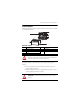
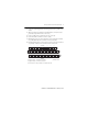
FLEX I/O 2-Channel Incremental Encoder Module 7 Install the Module Read this for information about how to install the module, which mounts on a 1794-TB3 or 1794-TB3S terminal base. 1 7 2 3 4 6 5 44341 Module Description 1 2 3 4 Description Latching mechanism Keyswitch Terminal base Groove 5 6 7 Description Alignment bar Module FlexBus connector ATTENTION: During mounting of all devices, be sure that all debris (such as metal chips or wire strands) is kept from falling into the module.
FLEX I/O 2-Channel Incremental Encoder Module 3. Make sure the pins on the bottom of the module are straight so they align properly with the connector in the terminal base. WARNING: If you remove or insert the module while the backplane power is on, an electrical arc can occur. This could cause an explosion in hazardous location installations. Be sure that power is removed or the area is nonhazardous before proceeding. 4.
FLEX I/O 2-Channel Incremental Encoder Module 9 3. Connect any signal wiring shields to functional ground as near as possible to the module. 4. When powering the encoder from the 1794-ID2 module, connect the encoder power lead to any terminal on the 34…51 row (C). 5. Connect +V DC power to terminal 34 on the 34…51 row (C). 6. Connec DC return to terminal 16 on the 16…33 (B). 7.
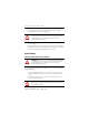
FLEX I/O 2-Channel Incremental Encoder Module 1794-TBN Terminal Base Wiring Even Numbered I/O Terminals 0…14 COM 16 COM 4 2 0 6 8 10 14 12 33 B 34 1 3 5 7 9 11 13 15 51 C +V +V Odd Numbered I/O Terminals 1…15 +V = Terminals C-34 and C-51 COM (-V) = Terminals B-16 and B-33 Wiring Connections for 1794-ID2 Signal Name Channel 0 A+ AB+ BZ+ ZG+ GChannel 1 A+ AB+ BZ+ ZG+ G0V DC COM 12/24V DC 1 1794-TB3, 1794-TB3S Signal 0V DC COM 12/24V DC 1794-TBN1 Signal A-0 A-1 A-2 A-3 A-4 A-5 A-
FLEX I/O 2-Channel Incremental Encoder Module 11 Example of Incremental Encoder Wiring Pulse Counter Channel 0 _ Signal for G counter gate + _ Signal for counter Z calibration/preset + _ Signal for up/down counting B + _ A + Signal inputs External power supply 12/24V DC 0V DC 12/24V DC 0 17 18 35 34 3 2 1 16 19 36 4 37 5 21 20 39 38 7 6 22 23 40 15 8 24 41 25 33 42 51 Example of pulse transmitter with 1 pulse train.
FLEX I/O 2-Channel Incremental Encoder Module Input (read) Image for 1794-ID2 Dec. Oct.
FLEX I/O 2-Channel Incremental Encoder Module 13 Output/Configuration Image for 1794-ID2 Dec. Oct.
FLEX I/O 2-Channel Incremental Encoder Module Description of Control Words 0 and 1 Bit 09…10 11…12 13 14 15 Description 10 09 0 0 0 1 1 0 1 1 12 11 Gate Control Bits No gate function on input G Counting only if G is high (active) Counting only if G is low (inactive) The counter can be calibrated when G is high (active) Store Control Bits - These bits will trigger a Store only if the channel Store status bit (S0 or S1) are cleared (0).
FLEX I/O 2-Channel Incremental Encoder Module 15 Specifications General Specification Attribute Number of inputs Number of inputs per counter Module Location Terminal base screw torque Dimensions, HxWxD (with module installed) Input pulse width, min Counting frequency, max Input range Input ON Input OFF Input current, typical Isolation voltage Flexbus current Power supply (external) Current consumption from external power supply Power dissipation, max Thermal dissipation, max Indicators (field side indica
FLEX I/O 2-Channel Incremental Encoder Module Environmental Specifications Attribute Value Temperature, operating IEC 60068-2-1 (Test Ad, Operating Cold), IEC 60068-2-2 (Test Bd, Operating Dry Heat), IEC 60068-2-14 (Test Nb, Operating Thermal Shock): 0…55 °C (32…131 °F) Note: Do not connect maximum input voltage simultaneously to all inputs if the module ambient temperature is expected to exceed 40 °C.
FLEX I/O 2-Channel Incremental Encoder Module 17 Certifications Certification (when product is marked)(1) c-UL-us CE C-Tick (1) Value UL Listed Industrial Control Equipment, certified for US and Canada. UL Listed for Class I, Division 2 Group A,B,C,D Hazardous Locations, certified for U.S. and Canada. European Union 2004/108/EC EMC Directive, compliant with: EN 61326-1; Meas./Control/Lab.
FLEX I/O 2-Channel Incremental Encoder Module Notes: Publication 1794-IN063C-EN-E - February 2014
FLEX I/O 2-Channel Incremental Encoder Module 19 Notes: Publication 1794-IN063C-EN-E - February 2014
Rockwell Automation Support Rockwell Automation provides technical information on the Web to assist you in using its products. At http://www.rockwellautomation.com/support/, you can find technical manuals, a knowledge base of FAQs, technical and application notes, sample code and links to software service packs, and a MySupport feature that you can customize to make the best use of these tools.