
Installation Instructions Owner's manual

4
Publication 1794-IN093C-EN-P - December 2009
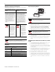
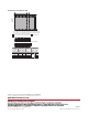
1794-TB32 or -TB32S Terminal Base Wiring for the 1794-IB32
Configure Your Input Module
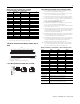
Configure your input module by setting bits in the configuration word (write word).
Set the Input Filter Time
To set the input filter time, set the associated bits in the output image table
(complementary word) for the module.
For example, to increase the off-to-on filter time to 4 ms for all inputs at address
rack 1, module group 0, (using 1794-IB32 as an example), set bits and program as
shown below.
Refer to the following Input Filter time chart for other bit settings.
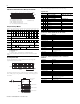
Input Filter Time
Specifications - 24V DC 8 Input Module, Cat. No. 1794-IB8
Specifications - 24V DC 16 Input Module, Cat. Nos. 1794-IB16 and
1794-IB16K
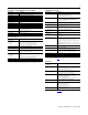
Dec. 15 14 13 12 11 10 9 8 7 6 5 4 3 2 1 0
Oct. 17 16 15 14 13 12 11 10 7 6 5 4 3 2 1 0
Read 1
(1794-IB16,
1794-IB32)
I15 I14 I13 I12 I11 I10 I9 I8 I7 I6 I5 I4 I3 I2 I1 I0
Read 1
(1794-IB8)
Not used I7 I6 I5 I4 I3 I2 I1 I0
Read 2
(1794-IB16)
C = Counter Input value of input 15
Read 2
(1794-IB32)
I31 I30 I29 I28 I27 I26 I25 I24 I23 I22 I21 I20 I19 I18 I17 I16
Write 1
(1794-IB8)
Not used Input Filter
0…07
Write 1
(1794-IB16)
Not used CF CR Not used Input Filter
12…15
Input Filter
0…11
Write 1
(1794-IB32)
Not used Input Filter FT
0…31
Not used
Where I = Input
C = Counter value for input 15
FT = Input filter time
CR = Counter reset
CF = Counter fast - where 1 = fast input (raw data), 0 = standard input filtered data
NOTE: C, CR and CF not available when used with any series 1794-ASB or 1794-ASB2 remote I/O adapter
modules.
+V1 COM1
17 18 19 20 21 22 23 24 25 26 27 28 29 30 31 32 33
0 1 2 3 4 5 6 7 8 9 10 11 12 13 14 15
16
35 36 37 38 39 40 41 42 43 44 45 46 47 48 49 50 51
34
NC
+V2 = Terminals 43, 45, 47, and 49
Inputs
+V1 COM1 +V1 COM1 +V1 COM1 +V2 COM2 +V2 COM2 +V2 COM2 +V2 COM2 NC
+V1 = Terminals 35, 37, 39, and 41
COM1 = Terminals 36, 38, 40, and 42
NC = No connections (terminals 16, 33, 34, and 51)
COM2 = Terminals 44, 46, 48, and 50
NC
NC
(1794-TB32 shown)
Inputs
15 14 13 12 11 10 9 8 7 6 5 4 3 2 1 0
FT = 0…7 (1794-IB8)
FT = 0…11 (1794-IB16)
1794-IB16
O:010
Dec.
15 14 13 12 11 10 9 8 7 6 5 4 3 2 1 0
17 16 15 14 13 12 11 10 7 6 5 4 3 2 1 0
Oct.
FT = 12…15
FT = 0…31
1794-IB32
1
00
76543
FLL
I:000
00
Fill File
Source
Destination
Length
#O:010
1
Write FT to complement
of input module.
Write filter time on system startup.
76 54 32 1 0
0
1
0
= 4 Octal or 4 Decimal
21 0
= 44 Octal or 36 Decimal
010100
1794-IB8
1794-IB16
1
00
= 4 Octal or 4 Decimal
10 0
1794-IB32
09 08101112131415
Bits Description - Filter Time Filter Time
02 01 00 Inputs 0…07 (1794-IB8) 1794-IB8, -IB16, -IB16K, -IB32
02 01 00 Inputs 0…11 (1794-IB16, -IB16K)
05 04 03 Inputs 12…15 (1794-IB16, -IB16K)
10 09 08 Inputs 0…31 (1794-IB32) Off to On/On to Off
0 0 0 Filter time 0 (default) 0.25 ms
0 0 1 Filter time 1 0.5 ms
0 1 0 Filter time 2 1 ms
0 1 1 Filter time 3 2 ms
1 0 0 Filter time 4 4 ms
1 0 1 Filter time 5 8 ms
1 1 0 Filter time 6 16 ms
1 1 1 Filter time 7 32 ms
Specification
Description
Number of inputs 8, nonisolated, sinking
Module location 1794-TB3 or 1794-TB3S terminal base unit
On-state voltage, min. 10V DC
On-state voltage, nom. 24V DC
On-state voltage, max. 31.2V DC
On-state current, min. 2.0 mA
On-state current, nom. 8.0 mA
On-state current, max. 12.0 mA
Off-state voltage, max. 5.0V DC
Off-state current, max. 1.5 mA
Input impedance 4.6K Ω
Isolation voltage 50V (continuous), Basic Insulation Type, between field side and system
No isolation between individual channels
Type tested at 850V DC for 60 s
Flexbus current 20 mA at 5V DC
Power dissipation 3.5W max. @ 31.2V DC
Thermal dissipation Max. 11.9 BTU/hr @ 31.2V DC
Specification
Description
Number of inputs 16 (1 group of 16), nonisolated, sinking
Module location 1794-TB3 or 1794-TB3S terminal base unit
Mounting Refer to the derating curve.
On-state voltage, min. 10V DC
On-state voltage, nom. 24V DC
On-state voltage, max. 31.2V DC
On-state current, min. 2.0 mA
On-state current, nom. 8.0 mA
On-state current, max. 12.0 mA
Off-state voltage, max. 5.0V DC
Off-state current, max. 1.5 mA
Input impedance 4.6K Ω
Isolation voltage 50V (continuous), Basic Insulation Type, between field side and system
No isolation between individual channels
Type tested at 707V DC for 60 s
Flexbus current 30 mA at 5V DC
Power dissipation 6.1W max. @ 31.2V DC
Thermal dissipation Max. 20.8 BTU/hr @ 31.2V DC