FLEX I/O System with ControlLogix for SIL 2 Catalog Number Bulletin 1794 Reference Manual
Important User Information Solid state equipment has operational characteristics differing from those of electromechanical equipment. Safety Guidelines for the Application, Installation and Maintenance of Solid State Controls (publication SGI-1.1 available from your local Rockwell Automation sales office or online at http://literature.rockwellautomation.com) describes some important differences between solid state equipment and hard-wired electromechanical devices.
Preface This application manual is intended to describe the FLEX I/O with ControlLogix Control System components available from Rockwell Automation that are suitable for use in SIL2 applications. Use this manual in conjunction with publication 1756-RM001 Introduction Alternate architecture can be used in SIL2 applications if they are approved by a certifying agency. This manual is designed to make clear how the FLEX I/O with ControlLogix Control System can be SIL2-certified. Table Preface.
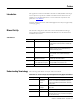
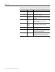
Preface 2 Table Preface.2 List of Acronyms Used Throughout the Safety Application Manual Publication 1794-RM001G-EN-P - December 2011 Acronym: Full Term: Definition: MTBF Mean Time Average time between failure occurrences. Between Failures MTTR Mean Time to Restoration PADT Programming and RSLogix 5000 software used to program and Debugging Tool debug a SIL2-certified FLEX I/O with ControlLogix application.
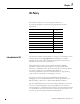
Chapter 1 SIL Policy This chapter introduces you to the SIL policy and how the ControlLogix/FLEX I/O system meets the requirements for SIL2 certification.
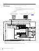
1-2 SIL Policy Figure 1.1 shows a typical SIL loop, including: SIL2 Certification • the overall safety loop • the ControlLogix/FLEX I/O portion of the overall safety loop • how other devices (for example, HMI) connect to the loop, while operating outside the loop Figure 1.1 Programming Software HMI For SIL applications, a programming terminal is not normally connected. For Diagnostics and Visualization (read-only access to controllers in the safety loop).
SIL Policy IMPORTANT 1-3 Important Note related to published PFDs. • The user must choose the appropriate PFD depending on combinations and the appropriate 1oo1 or 1oo2 configuration. • Descrete and analog inputs must be used in a 1oo2 configuration for SIL 2. • Adapters must be used in a 1oo2. • Outputs may be 1oo2 in series or 1oo1 monitored by an input with an external relay as a secondary device to remove power.
1-4 SIL Policy • Calibration of analog input and output modules to verify that accurate data is obtained from and used on the modules. IMPORTANT Users’ specific applications will determine the timeframe for the proof test interval. However, keep in mind that the Probability of Failure on Demand (PFD) calculations listed in Table 1.2 on page 1-8 use a proof test interval of once per year. If the proof test interval is changed, the information must be recalculated.
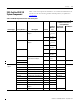
SIL Policy SIL2-Certified FLEX I/O System Components 1-5 Table 1.1 lists the components available for use in a SIL2-certified FLEX I/O system. For a list of ControlLogix SIL2 certified products, see publication 1756-RM001. Table 1.
1-6 SIL Policy Table 1.1 FLEX I/O Components For Use in the SIL 2 System Related Documentation(4) with More Information on Catalog Number: Firmware Revision: Device Type: I/O Modules Analog I/O Modules Analog Catalog Number: (1) Description: Series(2) Installation Instructions: User Manual: (2) (3) 1794-IE8 8 Input Analog Module B NA 1794-IN100 1794-UM002 1794-IF4I 4 Isolated Input Analog Module A F, G, H, I, I.
SIL Policy 1-7 Table 1.1 FLEX I/O Components For Use in the SIL 2 System Related Documentation(4) with More Information on Catalog Number: Firmware Revision: Device Type: Terminal Base Units Catalog Number: (1) Description: Series(2) Installation Instructions: User Manual: (2) (3) 1794-TB3 3-Wire Terminal Base Unit A NA 1794-TB3S 3-Wire Terminal Base Unit A NA 1794-TB3T Temperature Terminal Base Unit A NA 1794-TB3TS Spring-clamp Temperature Base Unit A NA 1794-TB3G Cage-clamp Gen.
1-8 SIL Policy Hardware Designs and Firmware Functions Diagnostic hardware designs and firmware functions designed into the ControlLogix/FLEX I/O platform allow it to achieve at least SIL2 certification in a single-controller configuration. These diagnostic features are incorporated into specific FLEX I/O components, such as the: • • • • adapter power supply I/O modules terminal base units and are covered in subsequent sections.
SIL Policy 1-9 Table 1.2 FLEX I/O Product Probability of Failure on Demand (PFD) Calculations (T1 = 1 yr) Catalog Number Description Mean Time Between Failure (MTBF)(1) λ(3) Calculated PFD 1oo2 architecture 1794-OB8EP Protected Output Module 2,389,669(2) 4.18E-07 7.54E-06 1794-OE4 Analog Output Module 23,807,086 4.20E-08 7.41E-07 1794-OF4I Isolated Analog Output Module 7,191,128 1.39E-07 2.47E-06 1794-OW8 Relay Output Module 14,766,876 6.77E-08 1.
1-10 SIL Policy Table 1.3 FLEX I/O Product Probability of Undetected Dangerous Failure per Hour (PFH) Calculations (T1 = 1 yr) Catalog Number Description Mean Time Between Failure (MTBF)(1) λ(3) Calculated PFH 1oo2 architecture 1794-ACN15 ControlNet Single Media Adapter 8,223,684 1.22E-07 8.64E-10 1794-ACNR15 ControlNet Redundant Media Adapter 8,223,684 1.22E-07 8.64E-10 1794-AENT 10/100Mb Ethernet Communication Adapter 691,134 1.45E-06 1.
SIL Policy 1-11 Table 1.3 FLEX I/O Product Probability of Undetected Dangerous Failure per Hour (PFH) Calculations (T1 = 1 yr) Catalog Number Description Mean Time Between Failure (MTBF)(1) λ(3) Calculated PFH 1oo2 architecture 1794-IE4XOE2XT 4 Input/2 Output Analog Combo Module 11,800,802 8.47E-08 5.99E-10 1794-IE8XT 8 Input analog Module 14,041,000 7.12E-08 5.03E-10 1794-OE4XT 4 Output Analog Module 11,381,744 8.79E-08 6.
SIL Policy 1794-ACNR15 (1) 1794-TB3 (1) 1756-L63B 1756-CNB 1756-CNB 1-12 1794-OB16 1794-IB16 B ControlNet 1794-ACNR15 (2) 1794-TB3 (2) 1794-IB16 B ControlNet Publication 1794-RM001G-EN-P - December 2011 1794-OW8
SIL Policy 1-13 SIL Compliance Distribution and Weight The programmable controller may conservatively be assumed to contribute 10% of the reliability burden. A SIL 2 system may need to incorporate multiple inputs for critical sensors and input devices, as well as dual outputs connected in series to dual actuators dependent on SIL assessments for the safety related system.
1-14 SIL Policy Notes: Publication 1794-RM001G-EN-P - December 2011
Chapter 2 ControlLogix Communications This chapter discusses the communication modules used in a ControlLogix SIL2 system. For information about: ControlNet Bridge Module See page: ControlNet Bridge Module 2-1 EtherNet/IP Bridge Module 2-1 Related Communications Modules Documentation 2-3 The ControlNet bridge modules (1756-CNB & 1756-CNBR) provide for the communications between ControlLogix and FLEX I/O system. ControlNet Cabling For remote racks, 802.
2-2 ControlLogix Communications EtherNet/IP Cabling 802.3 compliant shielded or unshielded twisted pair cable is required for EtherNet/IP. EtherNet/IP Module Diagnostic Coverage Communications over 10/100 MbpsNet media occur via CIP, which guarantees delivery of the data. All modules independently verify proper transmission of the data.
ControlLogix Communications 2-3 SlotStatusBits - This is a 32 bit value. The lower 8 bits of this value are defined as follows for FLEX I/O: Module 7 Related Communications Modules Documentation Module 6 Module 5 Module 4 Module 3 Module 2 Module 1 Module 0 For more information on ControlLogix communications modules, see the following Rockwell Automation publications listed in Table 2.1: Table 2.
2-4 ControlLogix Communications Publication 1794-RM001G-EN-P - December 2011
Chapter 3 FLEX I/O Modules This chapter discusses the FLEX I/O modules that are SIL2 certified.
3-2 FLEX I/O Modules Using Digital Input Modules General Considerations when using Any FLEX I/O Digital Input Module Regardless of the type of FLEX I/O input module used, there are a number of general application considerations that users must follow when applying these modules in a SIL2 application: • Proof Tests - Periodically (for example, once every several years) a System Validation test must be performed.
FLEX I/O Modules 3-3 The wiring diagrams in Figure 3.1 show two methods of wiring the digital input Module. In either case, users must determine whether the use of 1 or 2 sensors is appropriate to fulfill SIL2 requirements. Wiring FLEX I/O Digital Input Modules Figure 3.
3-4 FLEX I/O Modules The control, diagnostics and alarming functions must be performed in sequence. For more information on faults, see publication 1756-RM001.
FLEX I/O Modules 3-5 • Monitor the ControlNet status bits for the associated module and ensure that appropriate action is invoked via the application logic by these status bits. Wiring FLEX I/O Digital Output Modules Standard Digital Output Modules When using standard output modules, users must wire an output to an actuator and then back to an input to monitor the output’s performance.
3-6 FLEX I/O Modules Users can also wire a standard digital output module in series with an isolated relay output module in series with a critical actuator. In the event that a failure is detected, the output from both output modules must be set to OFF to guarantee the Output Loads de-energize. This is shown in Figure 3.6. Figure 3.
FLEX I/O Modules Using Analog Input Modules 3-7 General Considerations when using Any FLEX I/O Analog Input Module There are a number of general application considerations that you must follow when applying these modules in a SIL2 application: • Proof Tests - Periodically (for example, once every several years) a System Validation test must be performed. Manually, or automatically, test inputs to make sure that all inputs are operational.
3-8 FLEX I/O Modules The input’s OK bit preconditions a Timer run that is preset to accommodate an acceptable fault response time and any communication filtering lags in the system. If the inputs miscompare for longer than the preset value, a fault is registered with a corresponding alarm. Figure 3.
FLEX I/O Modules Wiring FLEX I/O Analog Input Modules 3-9 The wiring diagrams in show two methods of wiring the analog input Module. In either case, users must determine whether the use of 1 or 2 sensors is appropriate to fulfill SIL2 requirements. Figure 3.
3-10 FLEX I/O Modules Wiring the Single-Ended Input Module in Current Mode In addition to following the General Considerations when using Any FLEX I/O Analog Input Module on page 3-7, before wiring the module, consider the following application guideline: • Placement of Other Devices in Current Loop: you can locate other devices in an input channel’s current loop anywhere as long as the current source can provide sufficient voltage to accommodate all of the voltage drops (each module input is 250 ohms) 1
FLEX I/O Modules 3-11 Wiring the Thermocouple Input Module In addition to following the General Considerations when using Any FLEX I/O Analog Input Module on page 3-7, before wiring the module, consider the following application guideline: • Wire to Same Input Channel on Both Modules: When wiring thermocouples, wire two in parallel to two modules. Use the same channel on each module to make sure of consistent temperature readings. Figure 3.
3-12 FLEX I/O Modules Wiring the RTD Input Module In addition to following the General Considerations when using Any FLEX I/O Analog Input Module on page 3-7, before wiring the module, consider the following application guideline: • RTDs cannot be wired in parallel without severely affecting their accuracy. Two sensors must be used. Figure 3.
FLEX I/O Modules Using Analog Output Modules 3-13 General Considerations when using Any FLEX I/O Analog Output Module There are a number of general application considerations that you must follow when applying the analog output modules in a SIL2 application: • Proof Tests - Periodically (for example, once every several years) a System Validation test must be performed. Manually, or automatically, test outputs to make sure that all outputs are operational.
3-14 FLEX I/O Modules • Wire Output Back to Input and Examination of Output Data Feedback signal: Users must wire an analog output to an actuator and then back to an analog input to monitor the output’s performance. (The use of feedback transmitters to verify an output’s performance is acceptable.) The application logic must examine the Data Feedback value associated with each output point to make sure that the requested output command from the controller was received by the module.
FLEX I/O Modules 3-15 • When wiring two analog output modules in the same application, make sure: – Both modules use identical configuration. – The same controller owns both modules. • Monitor the ControlNet status bits for the associated module and ensure that appropriate action is invoked via the application logic by these status bits.
3-16 FLEX I/O Modules Wiring FLEX I/O Analog Output Modules In general, good design practice dictates that each analog output must be wired to a separate input terminal to make sure that the output is functioning properly. Wiring the Analog Output Module in Voltage Mode Users must wire analog outputs to an actuator and then back to an analog input to monitor the output performance.
FLEX I/O Modules 3-17 Wiring the Analog Output Module in Current Mode In addition to following the General Considerations when using Any FLEX I/O Analog Output Module on page 3-13, consider the following application guideline before wiring the module in current mode: • Placement of Other Devices in Current Loop: you can locate other devices in an output channel’s current loop anywhere as long as the current source can provide sufficient voltage to accommodate all of the voltage drops.
3-18 FLEX I/O Modules The following checklist is required for planning, programming and start up of SIL inputs. It may be used as a planning guide as well as during proof testing. If used as a planning guide, the checklist can be saved as a record of the plan. Checklist for SIL Inputs For programming or start-up, an individual checklist can be filled in for every single SIL input channel in a system. This is the only way to make sure that the requirements were fully and clearly implemented.
FLEX I/O Modules Checklist for SIL Outputs 3-19 The following checklist is required for planning, programming and start up of SIL outputs. It may be used as a planning guide as well as during proof testing. If used as a planning guide, the checklist can be saved as a record of the plan. For programming or start-up, an individual requirement checklist must be filled in for every single SIL output channel in a system.
3-20 FLEX I/O Modules Notes: Publication 1794-RM001G-EN-P - December 2011
Chapter 4 General Requirements for Application Software Refer to publication 1756-RM001, Using ControlLogix in SIL2 Applications.
4-2 General Requirements for Application Software Notes: Publication 1794-RM001G-EN-P - December 2011
Chapter 5 Technical SIL2 Requirements for the Application Program Refer to publication 1756-RM001 for Technical SIL2 Requirements for the application program.
5-2 Technical SIL2 Requirements for the Application Program Notes: Publication 1794-RM001G-EN-P - December 2011
Appendix A Failure Estimates The following tables list the failure estimates for the FLEX I/O products included in this manual for different proof test intervals. Table A.1 MTBF Field Data and Per Module PFD Estimates - T1 = 1 year Catalog Number: Description: (MTBF)(1) λ (3) Estimated PFD 1oo2 1794-ACN15 ControlNet Single Media Adapter 8,223,684 1.22E-07 2.15E-06 1794-ACNR15 ControlNet Redundant Media Adapter 8,223,684 1.22E-07 2.
A-2 Failure Estimates Table A.1 MTBF Field Data and Per Module PFD Estimates - T1 = 1 year Catalog Number: Description: (MTBF)(1) λ (3) Estimated PFD 1oo2 1794-AENTRXT 10/100Mb Ethernet Redundant Communication Adapter 1,268,070 7.89E-07 1.45E-05 1794-OB8EPXT 8 Protected Output Module 14,771,049 6.77E-08 1.20E-06 1794-IB16XT 16 Sink Input Module 35,587,189 2.81E-08 4.95E-07 1794-OB16PXT 16 Protected Output Module 26,709,401 3.74E-08 6.
Failure Estimates A-3 Table A.2 MTBF Field Data and Per Module PFD Estimates - T1 = 2 years Catalog Number: Description: (MTBF)(1) λ (3) Estimated PFD 1oo2 1794-IT8 Thermocouple Input Module 1,564,324 6.39E-07 2.41E-05 1794-OB16 16 Source Output Module 1,883,594 5.31E-07 1.98E-05 1794-OB16P Protected Output Module 2,135,280 4.68E-07 1.73E-05 1794-OB8EP Protected Output Module 2,389,669(2) 4.18E-07 1.54E-05 1794-OE4 Analog Output Module 23,807,086 4.20E-08 1.
A-4 Failure Estimates Table A.3 MTBF Field Data and Per Module PFD Estimates - T1 = 5 years Catalog Number: Description: (MTBF)(1) λ (3) Estimated PFD 1oo2 1794-ACN15 ControlNet Single Media Adapter 8,223,684 1.22E-07 1.10E-05 1794-ACNR15 ControlNet Redundant Media Adapter 8,223,684 1.22E-07 1.10E-05 1794-AENT 10/100Mb Ethernet Communication Adapter 691,134 1.45E-06 1.79E-04 1794-AENTR 10/100Mb Ethernet Redundant Communication Adapter 1,268,070 7.89E-07 8.
Failure Estimates A-5 Table A.3 MTBF Field Data and Per Module PFD Estimates - T1 = 5 years Catalog Number: Description: (MTBF)(1) λ (3) Estimated PFD 1oo2 1794-IB10XOB6XT 10 Input/6 Output Combo Module 22,202,487 4.50E-08 4.00E-06 1794-OW8XT 8 Relay Output Module 18,518,519 5.40E-08 4.81E-06 1794-IE4XOE2XT 4 Input/2 Output Analog Combo Module 11,800,802 8.47E-08 7.61E-06 1794-IE8XT 8 Input analog Module 14,041,000 7.12E-08 6.
A-6 Failure Estimates Table A.4 MTBF Field Data and Per Module PFH Estimates - T1 = 1 year Catalog Number: Description: (MTBF)(1) λ (3) Estimated PFH 1oo2 1794-OE4 Analog Output Module 23,807,086 4.20E-08 2.96E-10 1794-OF4I Isolated Analog Output Module 7,191,128 1.39E-07 9.90E10 1794-OW8 Relay Output Module 14,766,876 6.77E-08 4.78E-10 1794-TB3 Terminal Base Units 21,128,346(2) 4.73E-08 3.33E10 1794-TB3G Generic Terminal Base Units 27,320,800 3.66E-08 2.
Failure Estimates A-7 Table A.5 MTBF Field Data and Per Module PFH Estimates - T1 = 2 years Catalog Number: Description: (MTBF)(1) λ (3) Estimated PFH 1oo2 1794-ACN15 ControlNet Single Media Adapter 8,223,684 1.22E-07 8.76E-10 1794-ACNR15 ControlNet Redundant Media Adapter 8,223,684 1.22E-07 8.76E-10 1794-AENT 10/100Mb Ethernet Communication Adapter 691,134 1.45E-06 6.58E-09 1794-AENTR 10/100Mb Ethernet Redundant Communication Adapter 1,268,070 7.89E-07 6.
A-8 Failure Estimates Table A.5 MTBF Field Data and Per Module PFH Estimates - T1 = 2 years Catalog Number: Description: (MTBF)(1) λ (3) Estimated PFH 1oo2 1794-IB10XOB6XT 10 Input/6 Output Combo Module 22,202,487 4.50E-08 3.19E-10 1794-OW8XT 8 Relay Output Module 18,518,519 5.40E-08 3.83E-10 1794-IE4XOE2XT 4 Input/2 Output Analog Combo Module 11,800,802 8.47E-08 6.05E-10 1794-IE8XT 8 Input analog Module 14,041,000 7.12E-08 5.
Failure Estimates A-9 Table A.6 MTBF Field Data and Per Module PFH Estimates - T1 = 5 years Catalog Number: Description: (MTBF)(1) λ (3) Estimated PFH 1oo2 1794-OB16P Protected Output Module 2,135,280 4.68E-07 4.21E-09 1794-OB8EP Protected Output Module 2,389,669(2) 4.18E-07 3.68E-09 1794-OE4 Analog Output Module 23,807,086 4.20E-08 3.02E-10 1794-OF4I Isolated Analog Output Module 7,191,128 1.39E-07 3.76E-10 1794-OW8 Relay Output Module 14,766,876 6.77E-08 4.
A-10 Failure Estimates Notes: Publication 1794-RM001G-EN-P - December 2011
Index A Analog input modules 3-7–3-8 Analog output modules 3-13–3-15 Application program Technical SIL2 requirements 5-1 C Calibration 3-7, 3-13 Communication ControlNet 2-1 Communications modules 2-1 ControlNet module 2-1 Documentation 2-3 Control and information protocol Definition Preface-1 ControlNet module 2-1 Wiring analog input modules 3-9–3-15 Wiring analog output modules 3-16– 3-17 Wiring digital input modules 3-3 Wiring digital output modules 3-5, 3-6 M Mean time between failures (MTBF) Defin
2 Index Wiring I/O modules Analog input modules 3-9–3-15 Analog output modules 3-16–3-17 Publication 1794-RM001G-EN-P - December 2011 Digital input modules 3-3 Digital output modules 3-5, 3-6
Rockwell Automation Support Rockwell Automation provides technical information on the Web to assist you in using its products. At http://www.rockwellautomation.com/support/, you can find technical manuals, a knowledge base of FAQs, technical and application notes, sample code and links to software service packs, and a MySupport feature that you can customize to make the best use of these tools.