Installation Instructions FlexLogix Controller System Catalog numbers 1794-L33, 1794-L34, 1794-FLA Use this document as a guide for installing your FlexLogix™ controller system. This document provides installation instructions for both the FlexLogix controller (1794-L33, -L34) and the FlexLogix extended-local I/O adapter (1794-FLA). You should already be familiar with the FlexLogix system components. See the documentation references for additional information.
FlexLogix Controller System Important User Information Solid state equipment has operational characteristics differing from those of electromechanical equipment. Safety Guidelines for the Application, Installation and Maintenance of Solid State Controls (Publication SGI-1.1 available from your local Rockwell Automation sales office or online at http://www.ab.com/manuals/gi) describes some important differences between solid state equipment and hard-wired electromechanical devices.
FlexLogix Controller System 3 Environment and Enclosure ATTENTION This equipment is intended for use in a Pollution Degree 2 industrial environment, in overvoltage Category II applications (as defined in IEC publication 60664-1), at altitudes up to 2000 meters without derating. This equipment is considered Group 1, Class A industrial equipment according to IEC/CISPR Publication 11.
FlexLogix Controller System European Hazardous Location Approval European Zone 2 Certification (The following applies when the product bears the EEx Marking) This equipment is intended for use in potentially explosive atmospheres as defined by European Union Directive 94/9/EC.
FlexLogix Controller System 5 North American Hazardous Location Approval The following information applies when operating this equipment in hazardous locations: Informations sur l’utilisation de cet équipement en environnements dangereux : Products marked “CL I, DIV 2, GP A, B, C, D” are suitable for use in Class I Division 2 Groups A, B, C, D, Hazardous Locations and nonhazardous locations only.
FlexLogix Controller System The following information applies when operating this equipment in hazardous locations: WARNING EXPLOSION HAZARD • Do not disconnect equipment unless power has been removed or the area is known to be nonhazardous. • Do not disconnect connections to this equipment unless power has been removed or the area is known to be nonhazardous.
FlexLogix Controller System 7 Removal and Insertion Under Power The FlexLogix controller, the extended-local I/O adapter, the communication daughtercards, and the I/O terminal bases cannot be removed or inserted under power.. However, you can remove and insert FLEX I/O modules while backplane power is applied and the system is operating. WARNING If you insert or remove the module while backplane power is on, an electrical arc can occur. This could cause an explosion in hazardous location installations.
FlexLogix Controller System What You Need to Do Before you can install a FlexLogix controller or extended-local adapter, you must: ✓ Install steel, 35 x 7.55mm DIN rails (A-B part number 199-DR1; 46277-3) where you want to place the FlexLogix system components. The DIN rails for all FlexLogix system components, including all local and extended-local I/O modules, must be mounted on a common, conductive surface to ensure proper electromagnetic interference (EMI) performance.
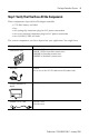
FlexLogix Controller System 9 Step 1: Verify That You Have All the Components These components ship with the FlexLogix controller: • • • • • 1756-BA1 battery and label key one spring-clip connector plug for 24V power connection one screw-terminal connector plug for 24V power connection two 1492-EA35 DIN rail locks The system components you have depend on your application.
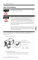
FlexLogix Controller System Step 2: Install the Battery ATTENTION WARNING Only install a 1756-BA1 battery. If you install a different battery, you may damage the controller. For safety information on the handling of lithium batteries, including the handling and disposal of leaking batteries, see Guidelines for Handling Lithium Batteries, publication AG-5.4. Store batteries in a cool, dry environment. We recommend 25°C with 40% to 60% relative humidity.
FlexLogix Controller System 11 Step 3: Install Communication Daughtercards (optional) WARNING If you insert or remove the card while host power is on, an electrical arc can occur. This could cause an explosion in hazardous location installations. For specific information about configuring the communication card (such as setting a node address), see the installation instructions for the communication card. 1. Turn off power to the controller. 2.
FlexLogix Controller System Step 4: Install the Controller 1. Position the FlexLogix controller on the DIN rail at a 5° angle and rotate the controller onto the DIN rail. A A locking tabs IMPORTANT You can mount the FlexLogix controller either vertically or horizontally (as shown). 2. Press the controller down onto the DIN rail until flush. The locking tabs will snap into position and lock the controller onto the DIN rail.
FlexLogix Controller System 13 4. Make sure power is not applied to the power supply. 5. Connect the power supply to the controller. The graphic below and its related instructions describe a 1794-PS13 power supply. WARNING If you connect or disconnect wiring while the field-side power is on, an electrical arc can occur. This could cause an explosion in hazardous location installations. Be sure that power is removed or the area is nonhazardous before proceeding. + _ A + _ C B D E F G H a.
FlexLogix Controller System 6. Mount the I/O terminal bases on the DIN rail. A B A 31036-M For information about I/O terminal bases, see the FLEX I/O Terminal Base Installation Instructions, publication 1794-IN092. 7. Install the I/O modules. To install an I/O module, see the installation instructions for that module. Removing the controller If you need to remove the controller, follow these steps: 1. Turn off power to the controller. 2. Disconnect all cables from the controller. 3.
FlexLogix Controller System 15 Step 5: Install the Extended-Local Adapter (optional) 1. Position the 1794-FLA extended-local I/O adapter on the DIN rail at a 30° angle and rotate the adapter onto the DIN rail. 2. Press the adapter down onto the DIN rail until flush. The locking tab will snap into position and lock the adapter onto the DIN rail. If the adapter does not lock in place, use a screwdriver or similar device to move the locking tab down while pressing the adapter onto the DIN rail.
FlexLogix Controller System 4. Make sure power is not applied to the power supply. Connect the power supply to the adapter. This diagram and its related instructions describe a 1794-PS13 power supply. a. Connect +24V dc input to the left adapter connector, terminal A, to the bottom, left power connector, terminal G. b. Connect -24V common to left adapter connector, terminal B, to the top, left power connector, terminal E. c.
FlexLogix Controller System 17 7. Connect the adapter to the controller. LOCAL rail 1794-CE1 or 1794-CE3 cable LOCAL2 rail 31039-M The following diagram shows how you can also use the 1794-CE1, -CE3 cable to split a rail of I/O. You can split each rail only once. You can split a rail right after the controller (or adapter) or after any I/O module. For more information about the 1794-CE1, -CE3 cables, see the Interconnect Cable Installation Instructions, publication 1794-5.12.
FlexLogix Controller System Make an RS-232 Connection to the Controller The RS-232 port is a non-isolated serial port built-in to the front of the controller. serial port To connect to the serial port: 1. Determine whether you need an optical isolator. If you connect the controller to a device outside of the system’s enclosure, consider installing an isolator between the controller and device. One possible isolator is the 1761-NET-AIC interface converter.
FlexLogix Controller System 19 2. Select the appropriate cable. Are you using an isolator? no Use this cable: The 1756-CP3 cable attaches the controller directly to the controller. 1 CD 1 CD 2 RDX 2 RDX 3 TXD 3 TXD 4 DTR 4 DTR COMMON COMMON 6 DSR 6 DSR 7 RTS 7 RTS 8 CTS 8 CTS 9 9 If you make your own cable, it must be shielded and the shields must be tied to the metal shell (that surrounds the pins) on both ends of the cable.
FlexLogix Controller System 3. Connect the appropriate cable to the serial port on the controller. WARNING If you connect or disconnect the serial cable with power applied to this module or the serial device on the other end of the cable, an electrical arc can occur. This could cause an explosion in hazardous location installations. Be sure that power is removed or the area is nonhazardous before proceeding. 4. If necessary, attach the controller to the isolator.
FlexLogix Controller System 21 Select the Operating Mode of the Controller 1.
FlexLogix Controller System Monitor the Controller LEDs Indicator: Color: Description: RUN off • no task(s) running • controller in Program mode green • one or more tasks are running • controller is in Run mode OK off no power applied red flashing after initially installing the controller - the controller requires a FLASH upgrade to the proper firmware revision; see below.
FlexLogix Controller System 23 Update the Controller RSLogix 5000 software, revision 10.0 or later, lets you update controller firmware as part of the download sequence. To update the controller, download your project and follow the prompts of the software. TIP 1. Connect the controller to the same network as your workstation. 2. Start ControlFLASH software. 3. Choose Next >. 4. Select the catalog number of the controller and choose Next >. 5. Expand the network until you see the controller.
FlexLogix Controller System FlexLogix Controller Approximate Mounting Dimensions 104.57mm (4.12in) 199.49mm (7.85in) 185.3mm (7.30in) 84.9mm (3.34in) 8.85mm (0.35in) 121.97mm (4.81in) 6.0mm (0.24in) 101.49mm (3.99in) 88.57mm (3.49in) 101.6mm (4.00in) 13.5mm (0.53in) 6.4mm (0.25in) 50.43mm (1.99in) 105.96mm (4.17in) 8.25mm (0.33in) 182.96mm (7.203in) 87.24mm (3.43in) 64.36mm (2.53in) 88.57mm (3.49in) 80.14mm (3.16in) 92.96mm (3.
FlexLogix Controller System 25 FlexLogix Extended-Local I/O Adapter Approximate Mounting Dimensions 94mm (3.7in) 117.12mm (4.61in) 69mm (2.72in) 88.94mm (3.5in) 81.06mm (3.19in) Approximate Mounting Clearance 25.4 mm (1 in) 25.4 mm (1 in) 25.4 mm (1 in) 25.4 mm (1 in) 25.4 mm (1 in) 25.4 mm (1 in) 25.
FlexLogix Controller System Other Publications You can use the following manuals with this product: Documents required for installation details: Publication number: Industrial Automation Wiring and Grounding Guidelines 1770-4.1 Flex 1794-PS3 Power Supply Installation Instructions 1794-5.71 Flex 1794-PS13 Power Supply Installation Instructions 1794-5.69 Flex I/O Terminal Base Installation Instructions 1794-5.16 1794-CE1, -CE3 Interconnect Cable Installation Instructions 1794-5.
FlexLogix Controller System Category: power supply FlexLogix controller (1794-L33, -L34) ! power conductors 27 FlexLogix extended-local I/O adapter (1794-FLA) 1794-PS3 or 1794-PS13 – In applications that must be compliant with CSA requirements, use a Separated Extra-Low Voltage (SELV) power supply that is compliant with IEC 61010.1, Annex H 60° C (140° F) minimum, copper #22 to #14 AWG (0.324 to 2.08 sq. mm) stranded 3/64 inch (1.
Category: FlexLogix controller (1794-L33, -L34) radiated RF immunity IEC 61000-4-3: 10V/m with 1kHz sine-wave 80%AM from 30MHz to 2000MHz 10V/m with 200Hz 50% Pulse 100%AM at 900Mhz EFT/B immunity IEC 61000-4-4: ±4kV at 2.