
Installation Instructions User Manual


3
Publication 1794-IN110A-EN-P - August 2005
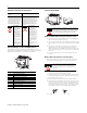
8. If the adapter module does not lock in place, use a screwdriver or
similar device to move the locking tab down while pressing the
adapter module flush onto the DIN rail, and release the locking tab to
lock the adapter module in place. If necessary, push up on the locking
tab to lock.
9. Reinstall the module in the adjacent terminal base unit.
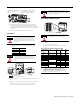
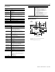
Connect Wiring
1. Connect the remote I/O cable to the removable remote I/O
connector.
2. Connect +V dc power to the left side of the lower connector, terminal
A.
3. Connect -V common to the left side of the upper connector, terminal
B.
4. Connections C and D are used to pass +V dc power (D) and -V
common (C) to the next module in the series (if required).
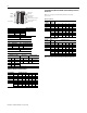
Set the Addressing Mode Switches
1. Lift the hinged switch cover on the front of the adapter to expose the
switches.
2. Set the switches as shown below.
3. Cycle power to the adapter after setting the switches.
8 and 16-point Mode Switch Settings
WARNING
If you connect or disconnect the communications
cable with power applied to this module or any
device on the network, an electrical arc can occur.
This could cause an explosion in hazardous location
installations.
Connect To terminal
Blue Wire - RIO 1
Shield Wire - RIO SH
Clear Wire - RIO 2
ATTENTION
If this is the last adapter, you must terminate the
remote I/O link here. Use a terminating resistor
connected across terminals 1 and 2. Refer to your
processor manual for information on the size of the
resistor.
C
Push down and in at the same
time to lock the adapter to the
DIN rail.
When the adapter is locked onto the DIN
rail, gently push the flexbus connector into
the adapter to complete the backplane
20127
1
SH
2
B
D
A
20131_LT
24V
COM
Allen-Bradley
ADAPTER
ACTIVE FAULT
LOCAL
FAULT
Termination resistor (if required)
82 W or 150 W (refer to your
processor documentation for size and usage)
PWR
C
1794-ASBLT
ATTENTION
To reduce susceptibility to noise, power analog
modules and digital modules from separate power
supplies. Do not exceed a total length of 32.8 ft
(10m) for dc power cabling.
ATTENTION
Some switches on this adapter differ from the
switches on previous versions. Make certain that
you identify each switch before setting.
When using this
addressing
mode
And Mode
Switch 2
S1-1
Mode
Switch 1
S2-5
Mode
Switch 0
S2-8
Standard (as
shipped
8 and/or 16-point
modules
See note
1
ON ON
Compact 8-point modules OFF ON OFF
16-point modules ON ON OFF
Complementary See complementary table below.
Primary Chassis 8-point modules OFF OFF ON
Complementary
Chassis
ON OFF ON
Complementary See complementary table below.
Primary Chassis 16-point modules OFF OFF OFF
Complementary
Chassis
ON OFF OFF
1 In Standard mode, this switch retains its function as switch position 1 of
rack addressing. In standard mode, the module is functionally
interchangeable with 1794-ASB series A or B adapters.
2 In compact mode, 32-point modules appear as 8 or 16-point modules.
3 When programming block transfers, address analog modules as module 0
if switch S1-1 is on; module 1 if switch S1-1 is off.
87654321
87654321
S1
S2
Flip
open
cover
on
on