
Owner manual
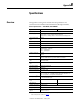
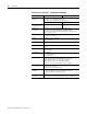


Table Of Contents
- 1794-UM066A-EN-P FLEX I/O Dual Port EtherNet/IP Adapter Modules User Manual
- Important User Information
- Preface
- Table of Contents
- 1 - Overview of FLEX I/O and Your Redundant EtherNet/IP Adapter Module
- Overview
- The FLEX I/O System
- Adapter Features
- Types of Adapters
- Hardware and Software Compatibility
- What the Adapter Does
- Use of the Control and Information Protocol (CIP)
- Understanding the Producer/Consumer Model
- Specifying the Requested Packet Interval (RPI)
- Support of Rack Optimized and Direct Connections
- Chapter Summary
- 2 - Install Your FLEX I/O Adapter
- 3 - Configure the Adapter for Your EtherNet/IP Network
- 4 - Rack Optimized Discrete I/O
- 5 - Analog I/O with Direct Connection
- A - Interpret Status Indicators
- B - Specifications
- C - Configure the RSLinx Ethernet Communication Driver
- D - Adapter Web Dialogs
- Index
- Back Cover
53 Publication 1794-UM066A-EN-P - February 2012
Appendix
B
Specifications
Overview
This appendix contains general and environmental specifications and
certifications for the FLEX I/O Dual Port EtherNet/IP Adapter Modules.
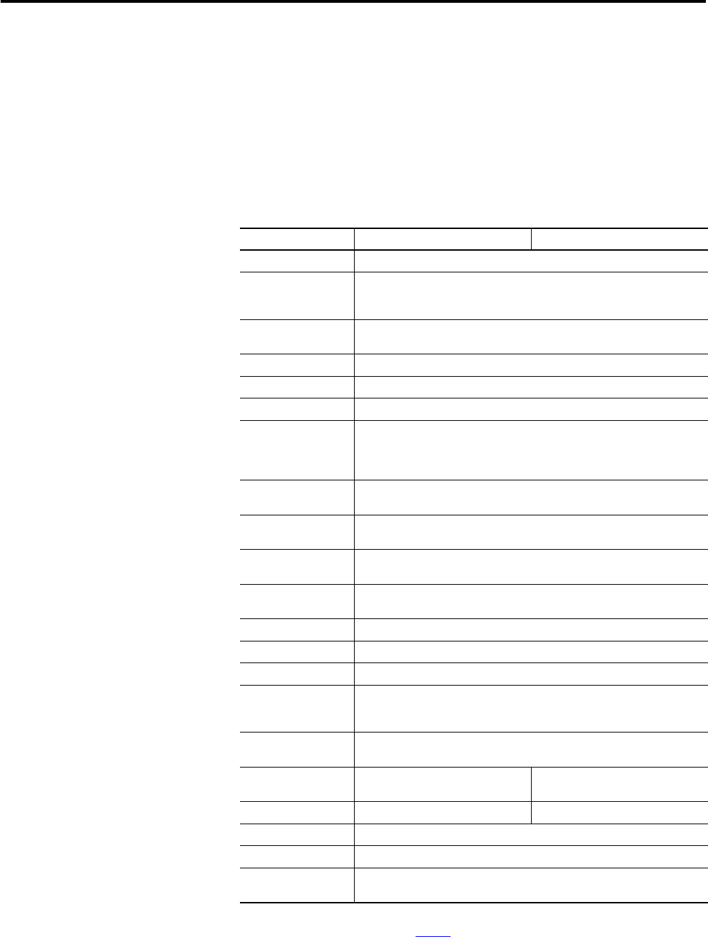
General Specifications – 1794-AENTR, 1794-AENTRXT
Specification 1794-AENTR 1794-AENTRXT
I/O capacity 8 modules
Power supply To comply with the CE Low Voltage Directive (LVD), this equipment must be
powered from a source compliant with the following:
Safety Extra Low Voltage (SELV) or Protected Extra Low Voltage (PELV).
Input voltage rating,
nom
24V DC
Input voltage range 19.2…31.2V DC (includes 5% AC ripple)
Inrush current 18 A for 2 ms
Communication rate 10/100 Mbps
Indicators Module status – red/green
Network status – red/green
Link 1 – yellow/green
Link 2 – yellow/green
FlexBus output, max 5.0V DC
640 mA
Isolation voltage 50V (continuous), Basic Insulation Type
Tested @ 1000V AC for 60 s, power to FlexBus to EtherNet
Power consumption,
max
500 mA,
400 mA @ 24V DC
Power dissipation,
max
7.1 W @ 19.2V DC
Thermal dissipation 24.2 BTU/hr @ 19.2V DC
Ethernet connector RJ45 Cat. 5
Enclosure type rating None (open-style)
Wire size Power conductors:
0.33…3.31 mm
2
(22…12 AWG) stranded copper wire rated @ 75 °C
(167 °F) or greater, 1.2 mm (3/64 in.) insulation max
Wiring category
(1)
(1)
Use this Conductor Category information for planning conductor routing. Refer to Industrial Automation Wiring
and Grounding Guidelines, publication 1770-4.1
.
1 – on power ports
2 – on communication ports
North American temp
code
T5 T4A
IEC temp code T5 T4
Terminal screw torque 0.8 Nm (7 lb-in.)
Weight, approx. 227 g (8.01 oz)
Dimensions, HxWxD,
approx.
87.4 x 94 x 92 mm
(3.44 x 3.7 x 3.6 in.)