
Owner manual
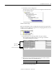
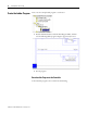
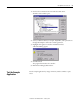
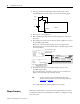
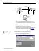
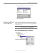
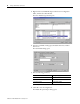
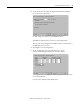
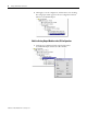
Table Of Contents
- 1794-UM066A-EN-P FLEX I/O Dual Port EtherNet/IP Adapter Modules User Manual
- Important User Information
- Preface
- Table of Contents
- 1 - Overview of FLEX I/O and Your Redundant EtherNet/IP Adapter Module
- Overview
- The FLEX I/O System
- Adapter Features
- Types of Adapters
- Hardware and Software Compatibility
- What the Adapter Does
- Use of the Control and Information Protocol (CIP)
- Understanding the Producer/Consumer Model
- Specifying the Requested Packet Interval (RPI)
- Support of Rack Optimized and Direct Connections
- Chapter Summary
- 2 - Install Your FLEX I/O Adapter
- 3 - Configure the Adapter for Your EtherNet/IP Network
- 4 - Rack Optimized Discrete I/O
- 5 - Analog I/O with Direct Connection
- A - Interpret Status Indicators
- B - Specifications
- C - Configure the RSLinx Ethernet Communication Driver
- D - Adapter Web Dialogs
- Index
- Back Cover
Publication 1794-UM066A-EN-P - February 2012
36 Rack Optimized Discrete I/O
1. Remove power from the FLEX I/O and wire inputs 0 and 2 of the
1794-IB16 FLEX I/O input module as shown in the following figure:
2. Restore power to the FLEX I/O.
3. Restore the RSLogix 5000 software window and place the controller in
Run mode.
4. Repeatedly press and release the momentary switch at Input 0 (Count) on
the 1794-IB16 input module.
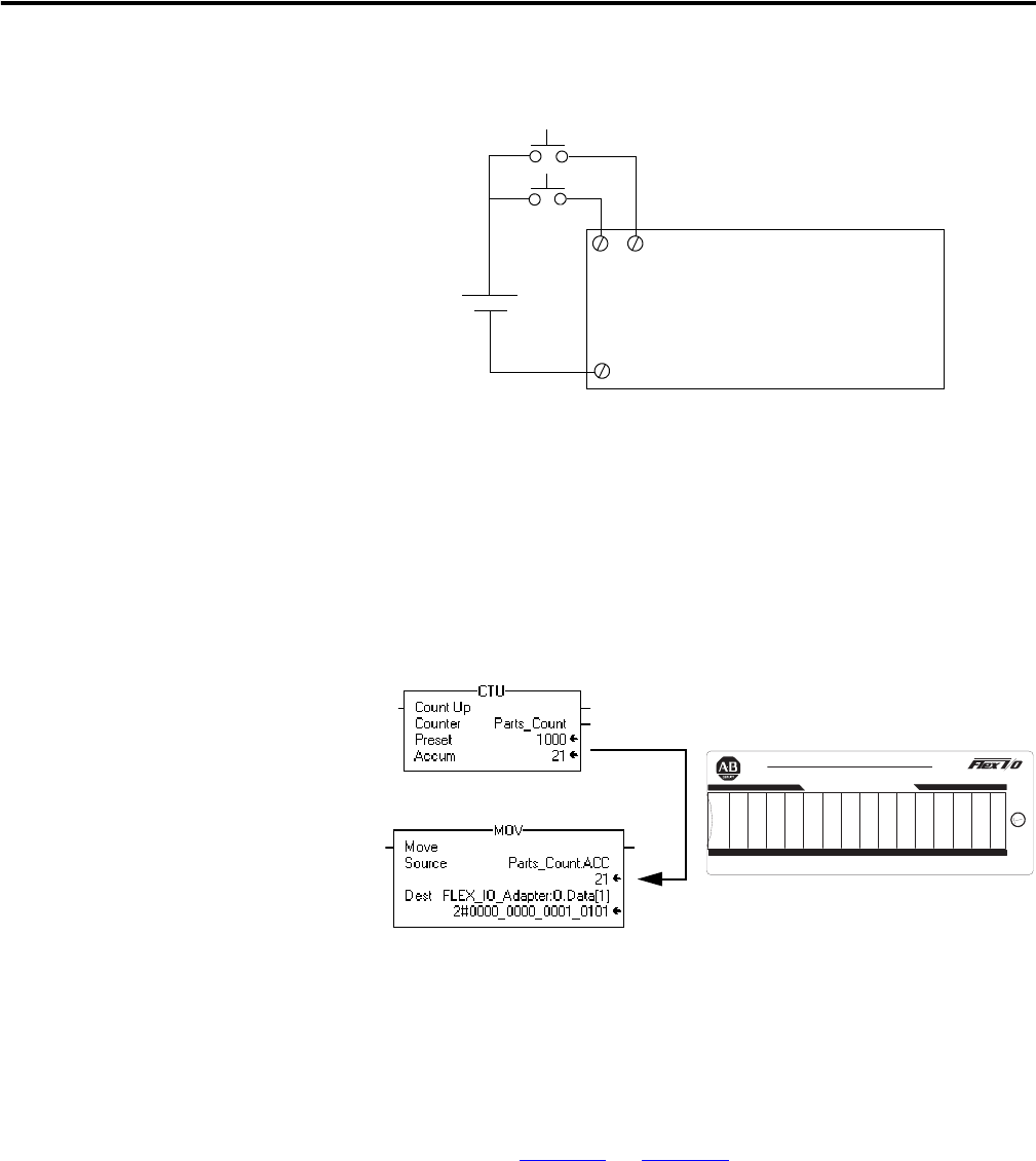
Each time you press the switch the Parts_Count accumulated value
increments on the screen and the LEDs of the 1794-OB16 output module
increment in binary.
5. Press and release the momentary switch at Input 2 (Reset) on the
1794-IB16 input module.
The accumulated value of the Parts_Count reset to zero and all of the
LEDs on the 1794-OB16 output module turn off.
This completes the Rack Optimized Discrete I/O example.
Chapter Summary
This chapter described how to set up and use rack optimized discrete I/O. The
next chapter describes how to add analog I/O modules to a configuration using
direct connection.
TIP
For more information on wiring and interpreting status LED
indicators on the I/O modules, refer to the I/O module publications
1794-IN093
and 1794-IN094.
Count
Reset
24V
+
-
1794-IB16
16 (COM)
02
151413121110987654321
0
24 VDC SOURCE OUTPUT
1794±OB16
2
Allen-Bradley
LEDs on Output Module will increment in binary.
Accumulated Value will
increment and move to
Output Module.