
Owner's manual

FLEX I/O ControlNet Redundant Media Adapter4
Publication
1794-5.18 – September 1996
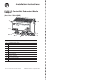
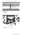
Wiring
AG
C
D
E
F
B
1. Connect the ControlNet network cable to connector, terminal A.
2. Connect the redundant ControlNet network cable to connector B.
3. Connect 24V common to the left side of the upper connector,
terminal C.
4. Connect +24V dc input to the left side of the lower connector,
terminal D.
5. Connections E and F are used to pass 24V dc power (F) and 24V
common (E) to the next module in the series (if required).
6. Set the network address using the 2-position thumbwheel switch G.
Valid settings range from 01 to 99. Press either the + or – buttons to
change the number.
Indicators