
Manual

Publication 1793-6.5.1 - April 1999
5-10 How Communication Takes Place and I/O Image Table Mapping with the DeviceNet Adapter
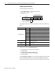
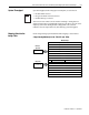
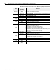
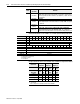
Analog Combo Module (1793-IE2XOE1 and -IE2XOE1S) Write Configuration Block
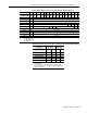
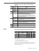
Range Selection Bits for the 1793-IE2XOE1 and -IE2XOE1S Analog Combo Module
Word 5
Bits 00-01
Underrange bits (U) for individual channels (4-20mA current input only)-
Bit 00 corresponds to input channel 0, bit 01 corresponds to input channel 1.
When set (1), indicates either a broken or open input wire, or input current at
or below 4mA.
Bits 02-03 Reserved
Bits 04
Wire Off bits (W) – Current outputs only – When set (1), the wire on the
current output is broken or the load resistance is too high. Bit 00 corresponds
to channel 0.
Bits 05-14
(05-16)
Reserved
Bit 15 (17)
Power Up bit - This bit is set to 1 when all bits in the configuration
register (write word 3) are 0 (unconfigured state). The configuration
register can be cleared by either a reset, or by the user writing all zeroes to it.
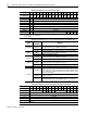
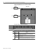
Word
Decimal Bit
(Octal Bit)
Definition
Word/Dec. Bit 15 14 13 12 11 10 09 08 07 06 05 04 03 02 01 00
Word/Octal Bit 17 16 15 14 13 12 11 10 07 06 05 04 03 02 01 00
Write Word 1 S Analog Data – Output Channel 0
Word 2 S Reserved
Word 3 0 Not used – set to 0 M0
Word 4 Not used C5 C4 C3 C2 C1 C0 0 0 0 F4 0 0 F1 F0
Words 5 and 6 Not used – set to 0
Word 7 Reserved
Word 8 Reserved
Word 9 Reserved
Word 10 Reserved
Where: M = Multiplex control bits
S = Sign bit (in 2’s complement)
C = Configure select bit
F = Full range bit
Channel No.
Input
Channel 0
Input
Channel 1
Output
Channel 0
F0 C0 F1 C1 F4 C4
Decimal Bits
(Octal Bits)
00
08
(10)
01
09
(11)
04
12
(14)
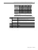
4-20mA 0 1 0 1 0 1
0-10V dc/0-20mA 1 0 1 0 1 0
–10 to +10V dc 1 1 1 1 1 1
Off
1
0 0 0 0 0 0
C = Configure select bit
F = Full range bit
1
When configured to off, individual channels will return 0000H.