
Manual

Publication 1793-6.5.1 - April 1999
How Communication Takes Place and I/O Image Table Mapping with the DeviceNet Adapter 5-7
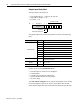
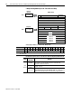
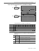
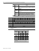
Analog Output Module (1793-OE2 and -OE2S) Write Configuration Block
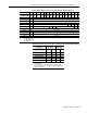
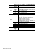
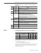
Range Selection Bits for the 1793-OE2 and -OE2S Analog Output Module (Word 5)
Word/Dec. Bit 15 14 13 12 11 10 09 08 07 06 05 04 03 02 01 00
Word/Octal Bit 17 16 15 14 13 12 11 10 07 06 05 04 03 02 01 00
Write Word 1 S Analog Data – Channel 0
Word 2 S Analog Data – Channel 1
Word 3 S Reserved
Word 4 S Reserved
Word 5 0 Not used – set to 0 M1 M0
Word 6 0 Not used – set to 0 C1 C0 Not used – set to 0 F1 F0
Word 7 thru 10 Not used – set to 0
Word 11 S Reserved
Word 12 S Reserved
Word 13 S Reserved
Word 14 S Reserved
Where: S = Sign bit (in 2’s complement)
M = Multiplex control
C = Configure select bit
F = Full range bit
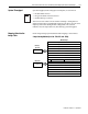
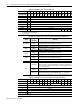
Channel No. Channel 0 Channel 1
F0 C0 F1 C1
Decimal Bits (Octal Bits) 00 08 (10) 01 09 (11)
4-20mA 0 1 0 1
0-10V dc/0-20mA 1 0 1 0
–10 to +10V dc 1 1 1 1
Off
1
0 0 0 0
C = Configure select bit
F = Full range bit
1
When configured to off, individual channels will send 0V or 0mV on
Series B modules. On Series A modules, 2V or 4mA is output until the
module is configured.