
Manual

Publication 1793-6.5.1 - April 1999
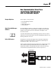
4-8 Writing Configuration to and Reading Status from Your Module with a Remote I/O Adapter
2 Input/1 Output Analog Combo Module (Cat. No. 1793-IE2XOE1 and -IE2XOE1S)
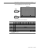
Analog Combo Module (1793-IE4XOE1) Read
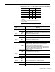
Word/Bit Descriptions for the 1794-IE4XOE1 and -IE2XOE1S Analog Combo
Module Read
Words 12-13
Bits 00-15
(00-17)
Reserved
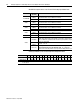
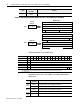
Word
Decimal Bit
(Octal Bit)
Definition
Module Image
I/O Image
Input Data Channel 0
Input Data Channel 1
Output Data Channel 0
Underrange & Diag.
Output Channel 0 Safe State
Not used
Not used Full Range and Configure Select
Not used
Input Size
Output Size
0 to 7 Words
0 to 5 Words
Read
Write
M
PU
Not used
Reserved
Reserved
Reserved
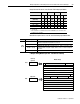
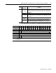
Word/Dec. Bit 15 14 13 12 11 10 09 08 07 06 05 04 03 02 01 00
Word/Octal Bit 17 16 15 14 13 12 11 10 07 06 05 04 03 02 01 00
Read Word 0 S Analog Value Input Channel 0
Word 1 S Analog Value Input Channel 1
Word 2 S
Word 3 S
Word 4 PU Not used – set to 0 W1 W0
Where: S = sign bit (in 2’s complement)
W = Diagnostic bits for current output wire broken or load resistance high. (Not used on voltage outputs.)
PU = Power up bit
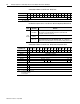
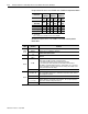
Word
Decimal Bit
(Octal Bit)
Definition
Read
Word 0
Bits 00-14
(00-16)
Channel 0 analog data – 12-bit left justified two’s complement number;
unused lower bits are zero; 4-20mA uses all 16 bits.
Bits 15 (17) Channel 0 analog data sign bit.
Word 1
Bits 00-14
(00-16)
Channel 1 analog data – 12-bit left justified two’s complement number;
unused lower bits are zero; 4-20mA uses all 16 bits.
Bits 15 (17) Channel 1 analog data sign bit.
Words 2
and 3
Reserved