
Manual

Publication 1793-6.5.1 - April 1999
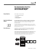
4-4 Writing Configuration to and Reading Status from Your Module with a Remote I/O Adapter
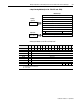
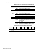
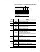
Word/Bit Descriptions for the 1793-IE4 and -IE4S Analog Input Module Read
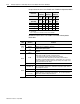
Analog Input Module (1793-IE4 and -IE4S) Write Configuration Block
Word
Decimal Bit
(Octal Bit)
Definition
Read Word 0
Bits 00-14
(00-16)
Channel 0 analog data – 12-bit left justified two’s complement number;
unused lower bits are zero; 4-20mA uses all 16 bits.
Bits 15 (17) Channel 0 analog data sign bit.
Word 1
Bits 00-14
(00-16)
Channel 1 analog data – 12-bit left justified two’s complement number;
unused lower bits are zero; 4-20mA uses all 16 bits.
Bits 15 (17) Channel 1 analog data sign bit.
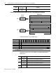
Word 2
Bits 00-14
(00-16)
Channel 2 analog data – 12-bit left justified two’s complement number;
unused lower bits are zero; 4-20mA uses all 16 bits.
Bits 15 (17) Channel 2 analog data sign bit.
Word 3
Bits 00-14
(00-16)
Channel 3 analog data – 12-bit left justified two’s complement number;
unused lower bits are zero; 4-20mA uses all 16 bits.
Bits 15 (17) Channel 3 analog data sign bit.
Words 4-7 Reserved
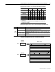
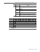
Word 8
Bits 00-03
Underrange bits (U) for individual channels (4-20mA current input only)-
Bit 00 corresponds to input channel 0, bit 01 corresponds to input channel 1,
and so on. When set (1), indicates either a broken or open input wire, or input
current at or below 4mA.
Bits 04-14
(04-16)
Not used – set to 0.
Bit 15 (17)
Power Up bit .- This bit is set to 1 when all bits in the configuration
register (write word 0) are 0 (unconfigured state). The configuration
register can be cleared by either a reset, or by the user writing all zeroes to it.
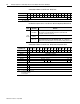
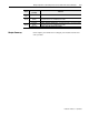
Word/Dec. Bit 15 14 13 12 11 10 09 08 07 06 05 04 03 02 01 00
Word/Octal Bit 17 16 15 14 13 12 11 10 07 06 05 04 03 02 01 00
Write Word 0 Reserved C3 C2 C1 C0 Reserved F3 F2 F1 F0
Where: C = Configure select bit
F = Full range bit