
Manual

Publication 1793-6.5.1 - April 1999
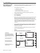
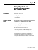
3-4 Module Programming
PLC-5 Programming
The PLC-5 program is very similar to the PLC-3 program with the
following exceptions:
• block transfer enable bits are used instead of done bits as the conditions
on each rung.
• separate block transfer control files are used for the block transfer
instructions.
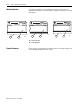
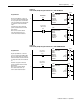
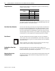
Figure 3.4
PLC-5 Family Sample Program Structure for the 1793-IE4
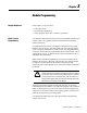
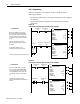
Figure 3.5
PLC-5 Family Sample Program Structure for the 1793-OE2
BTR Enable Bit
EN
DN
BTW Enable Bit
1
2
ER
EN
DN
ER
BTR
BTW
Program Action
N12:5
15
N12:0
15
Thereafter, the program continuously
performs read block transfers to configure
the module.
Pushbutton
The pushbutton allows the user to
manually request a block transfer write.
N13:8
15
Power-up
Bit
1
At power-up in RUN mode, or when the
processor is switched from PROG to RUN,
the user program enables a block transfer
read. Then it initiates a block transfer write
to configure the module if the power-up bit
is set.
1
Power-up bit included in Series B modules only.
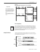
BTR Enable Bit
N12:0
15
BTW Enable Bit
N12:5
15
BLOCK TRANSFER READ
RACK: 2
GROUP: 1
MODULE: 0
CONTROL: N12:0
DATA FILE: N13:0
LENGTH: 9
CONTINUOUS: N
BLOCK TRANSFER WRITE
RACK: 2
GROUP: 1
MODULE: 0
CONTROL: N12:5
DATA FILE: N13:20
LENGTH: 1
CONTINUOUS: N
BTR Enable Bit
EN
DN
BTW Enable Bit
1
2
ER
EN
DN
ER
BTR
BTW
Program Action
N14:5
15
N14:0
15
Thereafter, the program continuously
performs read block transfers and write block
transfers.
At power-up in RUN mode, or when the
processor is switched from PROG to RUN,
the user program enables a block transfer
read. Then it initiates a block transfer write
to configure the module and send data val-
ues.
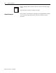
BTW Enable Bit
N14:5
15
BTR Enable Bit
N14:0
15
BLOCK TRANSFER READ
RACK: 2
GROUP: 2
MODULE: 0
CONTROL: N14:0
DATA FILE: N15:0
LENGTH: 1
CONTINUOUS: N
BLOCK TRANSFER WRITE
RACK: 2
GROUP: 2
MODULE: 0
CONTROL: N14:5
DATA FILE: N15:5
LENGTH: 14
CONTINUOUS: N