
Manual


Publication 1793-6.5.1 - April 1999
2-8 How to Install Your Analog Module
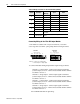
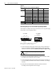
Table 2.B
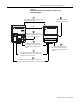
Wiring connections for the 1793-OE2 Analog Module
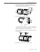
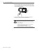
Connecting Wiring for the 1793-IE2XOE1 Input/Output Module
This module is available with 2 styles of connectors; screw-cage and spring
clamp. Refer to the wiring figure below.
1. Connect individual analog input channel signal wiring to terminals on
row A. Use terminals 2 (channel 0) and 4 (channel 1) for current and
terminals 3 and 5 for current. Use Belden 8761 cable for signal wiring..
2. Connect the associated channel common to common terminals 1 and 6
according to the wiring table on the next page.
3. Connect individual analog output channel signal wiring to terminals 10
or 11 on row B. (Use terminal 10 for current, or terminal 11 for voltage -
not both.)
4. Connect the associated channel common to common terminal 9
according to the wiring table on the next page.
Channel Type Label Marking Signal Return
0
Current Signal I 2
Current Common RET 1
Voltage Signal V 3
Voltage Common RET 1
1
Current Signal I 4
Current Common RET 6
Voltage Signal V 5
Voltage Common RET 6
24V dc Common Terminals 0, 1, 6, 7, 9 and 14
+24V dc Terminals 8 and 15 are internally connected to +V.
$77(17,21 &RQQHFWRQO\FXUUHQWRUYROWDJHVLJQDO
SHUFKDQQHO'RQRWFRQQHFWERWKFXUUHQWDQGYROWDJHRQ
FKDQQHO
1793-IE2XOE1
1793-IE2XOE1S
01234 567
8 9 10 11
A
B
13 14 1512
41473
CC
C
C
VV
C
C
V0 V1I1I0
VoIo
In Ch 0
In Ch 1
Out Ch 0
0 123456 7
8 9 10 11 12 13 14 15
A
B
41472
CC
VVCC
V0 V1I1I0
VoIo
CC
I
In Ch 0
In Ch 1
Out Ch 0
V
0,1
= voltage in; I
o
= current out; V
o
= voltage out
Where: C = common; V = +24V dc power; I
0,1
= current in;