
Manual


Publication 1793-6.5.1 - April 1999
2-6 How to Install Your Analog Module
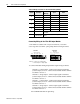
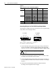
Table 2.A Wiring connections for the 1793-IE4 Analog Module
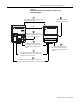
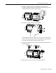
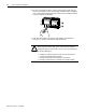
Connecting Wiring for the 1793-OE2 Output Module
. This module is available with 2 styles of connectors; 1793-OE2 -
screw-cage and 1793-OE2S - spring clamp. Refer to the figure below.
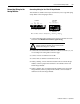
1. Connect individual analog output channel signal wiring as follows:
Channel 0 - Current output - connect output signal to terminal 2
(current output) on row A. Connect the associated channel common
to terminal 1 on row A.
Channel 0 - voltage output - connect output signal to terminal 3
(current output) on row A. Connect the associated channel common
to terminal 1 on row A.
Channel 1 - Current output - connect output signal to terminal 4
(current output) on row A. Connect the associated channel common
to terminal 6 on row A.
Channel 0 - voltage output - connect output signal to terminal 5
(current output) on row A. Connect the associated channel common
to terminal 6 on row A.
1RWH8VH%HOGHQFDEOHIRUVLJQDOZLULQJ
Channel Signal Type
Label
Markings
Signal Return
0
Current I 2 1
Voltage V 3 1
1
Current I 4 6
Voltage V 5 3
2
Current I 10 9
Voltage V 11 9
3
Current I 12 14
Voltage V 13 14
24V dc Common
Terminals 0, 1, 6, 9, and 14 are connected together in
the module.
+24V dc power
Terminals 8 and 15 are internally connected in the
module.
1793-OE4 1793-OE4S
0 123456 7
8 9 10 11 12 13 14 15
A
B
41359
CC
CVVC
V0I0 V1I1
Ch0 Ch1
CC
01234 567
8 9 10 11
A
B
13 14 1512
Out Ch 0 Out Ch 1
41358
I1 V1Io VoC
V
CCC
VCC
Where: C = common; V = +24V dc power;
I = current output; V = voltage output