
Manual


Publication 1793-6.5.1 - April 1999
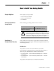
How to Install Your Analog Module 2-5
Connecting Wiring for the
Analog Modules
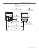
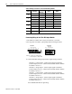
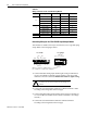
Connecting Wiring for the 1793-IE4 Input Module
This module is available with 2 styles of connectors; screw-cage and spring
clamp. Refer to the wiring figure below.
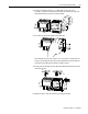
1. Connect individual analog channel signal wiring to terminals on row A
and row C. Use Belden 8761 cable for signal wiring..
2. Connect the associated channel common to common terminals 1, 6, 9 or
14 according to the wiring table on the next page.
3. Connect +24V dc to terminal 8 on row B.
4. Connect 24V dc common to terminal 0 on row A.
5. If daisy-chaining +24V dc from this module to the next FLEX Integra
module, connect a jumper from terminal 15 to terminal 8 on the next
FLEX Integra module.
6. If daisy-chaining 24V dc common from this module to the next FLEX
Integra module, connect a jumper from terminal 7 on this module to
terminal 0 on the next Integra module.
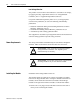
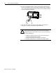
ATTENTION: Connect only 1 current or 1
voltage signal per channel. Do not connect both
current and voltage on 1 channel.
1793-IE4
1793-IE4S
01234 567
8 9 10 11
A
B
13 14 1512
41470
CC
C
C
VV
C
C
I1I0 V0 V1
I3I2 V2 V3
Ch 0 Ch 1
Ch 2 Ch 3
0 123456 7
8 9 10 11 12 13 14 15
A
B
41471
CC
VVCC
V1 V2I2I1
V3 V4I4I3
CC
Ch 0 Ch 1
Ch 2 Ch 3
Where: C = 24V dc common, V = 24V dc power, I
n
= current in, V
n
= voltage in