
Manual

Publication 1793-6.5.1 - April 1999
1-2 Overview of FLEX Integra and your Analog Modules
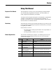
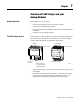
Types of FLEX Integra Modules We describe the following FLEX Integra Analog modules in this user
manual:
FLEX Integra analog input, output and combination modules are block
transfer modules that interface analog signals with any Allen-Bradley
programmable controllers that have block transfer capability. Block
transfer programming moves input from the module’s memory to a
designated area in the processor data table, and output data words from a
designated area in the processor data table to the module’s memory. Block
transfer programming also moves configuration words from the processor
data table to module memory.
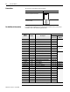
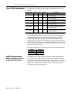
The analog modules have selectable ranges as shown in the table below:
How FLEX Integra Analog
Modules Communicate with
Programmable Controllers
The adapter/power supply transfers data to the module (block transfer
write) and from the module (block transfer read) using BTW and BTR
instructions in your ladder diagram program. These instructions let the
adapter obtain input values and status from the module, and let you send
output values and establish the module’s mode of operation. Figure 1.1
describes the communication process.
Catalog Number Voltage Inputs Outputs Description
1793-IE4 24V dc 4 –
analog – 4 input, single-ended, non-isolated;
screw-cage connectors
1793-IE4S 24V dc 4 –
analog – 4 input, single-ended, non-isolated;
spring-clamp connectors
1793-OE2 24V dc – 2
analog – 2 output, single-ended, non-isolated;
screw-cage connectors
1793-OE2S 24V dc – 2
analog – 2 output, single-ended, non-isolated;
spring-clamp connectors
1793-IE2XOE1 24V dc 2 1
analog – 2 input, single-ended, non-isolated
and 1 output, single-ended, non-isolated;
screw-cage connectiors
1793-IE2XOE1S 24V dc 2 1
analog – 2 input, single-ended, non-isolated
and 1 output, single-ended, non-isolated;
spring-clamp connectors
Voltage Current
0 to 10V dc 0 to 20mA
±10V dc 4 to 20mA