Allen-Bradley FLEX Integra Analog Modules (Cat. No.
Important User Information Because of the variety of uses for the products described in this publication, those responsible for the application and use of this control equipment must satisfy themselves that all necessary steps have been taken to assure that each application and use meets all performance and safety requirements, including any applicable laws, regulations, codes and standards.
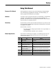
Preface Using This Manual Purpose of this Manual This manual shows you how to use your FLEX Integra Analog modules with Allen-Bradley programmable controllers. The manual helps you install, program and troubleshoot your modules. Audience You must be able to program and operate an Allen-Bradley programmable controller to make efficient use of your FLEX Integra modules. In particular, you must know how to program block transfers, and be familiar with DeviceNet or ControlNet software.
P-2 Using This Manual Conventions We use these conventions in this manual: In this manual, we show: Like this: that there is more information about a topic in another chapter in this manual that there is more information about the topic in another manual For Additional Information For additional information on FLEX Integra and FLEX I/O systems and modules, refer to the following documents: Publications Catalog Number Voltage 1793 Series 1793-IB4 1793-OB4P Description FLEX Integra Product Data
Using This Manual P-3 Publications Catalog Number Voltage 1794-IB10XOB6 24V dc 10 Input/6 Output Module 1794-5.24 1794-IE8 24V dc Selectable Analog 8 Input Module 1794-5.6 Description Installation Instructions 1794-OE4 24V dc Selectable Analog 4 Output Module 1794-5.5 1794-IE4XOE2 24V dc 4 Input/2 Output Analog Module 1794-5.15 1794-OF4 24V dc 4 Output Isolated Analog Module 1794-5.37 1794-IF4 24V dc 4 Input Isolated Analog Module 1794-5.38 User Manual 1794-6.5.2 1794-6.5.
Table of Contents Preface Using This Manual Purpose of this Manual . . . . . . . . . . . . . . . . . . . . . . . . . . . . . . . . . Audience . . . . . . . . . . . . . . . . . . . . . . . . . . . . . . . . . . . . . . . . . . . . Vocabulary . . . . . . . . . . . . . . . . . . . . . . . . . . . . . . . . . . . . . . . . . . Manual Organization . . . . . . . . . . . . . . . . . . . . . . . . . . . . . . . . . . Conventions . . . . . . . . . . . . . . . . . . . . . . . . . . . . . . . . . . . . . . . . .
ii Chapter 4 Writing Configuration to and Reading Status from Your Module with a Remote I/O Adapter Chapter Objectives . . . . . . . . . . . . . . . . . . . . . . . . . . . . . . . . . . . . 4-1 Configuring Your Analog Module . . . . . . . . . . . . . . . . . . . . . . . . 4-1 Range Selection. . . . . . . . . . . . . . . . . . . . . . . . . . . . . . . . . . . . . . . 4-2 Safe State Value Selection . . . . . . . . . . . . . . . . . . . . . . . . . . . . . . 4-2 Data Format. . . . . . . . . . . . . . . . .
iii Chapter 6 Input, Status, Output and Configuration Files using ControlNet What this Chapter Contains . . . . . . . . . . . . . . . . . . . . . . . . . . . . . 6-1 About the ControlNet Adapter . . . . . . . . . . . . . . . . . . . . . . . . . . . 6-1 Communication Over the FLEX I/O Backplane . . . . . . . . . . . . . . . . . . . . . . . . . . . . . . . . . . 6-1 Scheduled Data-Transfer . . . . . . . . . . . . . . . . . . . . . . . . . . . . 6-2 Unscheduled Data-Transfer . . . . . . . . . . . . . . . . .
Chapter 1 Overview of FLEX Integra and your Analog Modules Chapter Objectives The FLEX Integra System In this chapter, we tell you about: • what the FLEX Integra system is and what it contains • types of FLEX Integra analog modules • how FLEX Integra analog modules communicate with programmable controllers • the features of your analog modules FLEX Integra is a small, modular I/O system for distributed applications that performs all of the functions of rack-based I/O.
1-2 Overview of FLEX Integra and your Analog Modules Types of FLEX Integra Modules We describe the following FLEX Integra Analog modules in this user manual: Catalog Number Voltage Inputs Outputs 1793-IE4 24V dc 4 – 1793-IE4S 24V dc 4 – 1793-OE2 24V dc – 2 1793-OE2S 24V dc – 2 1793-IE2XOE1 24V dc 2 1 1793-IE2XOE1S 24V dc 2 1 Description analog – 4 input, single-ended, non-isolated; screw-cage connectors analog – 4 input, single-ended, non-isolated; spring-clamp connectors anal
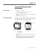
Overview of FLEX Integra and your Analog Modules 1-3 Figure 1.1 An Example of Communication Between an Adapter and an Analog Input Module 1 2 The adapter transfers your configuration data to the module using a BTW. External devices transmit analog signals to the module. Flexbus Allen-Bradley ADAPTER ACTIVE FAULT LOCAL FAULT Allen-Bradley 24VDC POWER SUPPLY RIO ADAPTER 1794-ASB 4 Your ladder program instructs the adapter to perform a BTR of the values and stores them in a data table.
1-4 Overview of FLEX Integra and your Analog Modules Features of your Analog Modules Each module has a unique label identifying its wiring and module type. A removable label provides space for writing individual designations per your application. 1793-IE4S 0 1 INPUT 2 A 1793-IE2XOE1 1793-OE2 4 INPUT ANALOG 2 CH ANALOG OUTPUT 2 INPUT/1 OUTPUT ANALOG INPUT 0 1 3 B 41350 41368 A B A OUTPUT 0 B 41491 A = status indicator B = insertable label Chapter Summary Publication 1793-6.5.
Chapter 2 How to Install Your Analog Module Chapter Objectives In this chapter, we tell you about: • how to install your module • how to wire your module • the indicators Before You Install Your Analog Module Before installing your analog module in the I/O chassis: You need to: Calculate the power requirements of all modules in each chassis.
2-2 How to Install Your Analog Module Low Voltage Directive This product is tested to meet Council Directive 73/23/EEC Low Voltage, by applying the safety requirements of EN 61131-2 Programmable Controllers, Part 2 – Equipment Requirements and Tests. For specific information required by EN 61131-2, see the appropriate sections in this publication, as well as the following Allen-Bradley publications: • Industrial Automation Wiring and Grounding Guidelines For Noise Immunity, publication 1770-4.
How to Install Your Analog Module 2-3 2. Position the module on the 35 x 7.5mm DIN rail A (A-B pt. no. 199-DR1). Rotate the module onto the DIN rail with the top of the rail hooked under the lip on the rear of the module. A A 30720-M 3. Press down to lock the module on the DIN rail.l A 41377 If the module does not lock in place, use a screwdriver of similar device to move the locking tab down, press the module flush with the DIN rail and release the locking tab to lock the module in place 4.
2-4 How to Install Your Analog Module 6. To remove an Integra module, you must work from the right side and remove one module at a time. To disengage a module from its neighbor, place a common flat-bladed screwdriver between the 2 modules and turn 1/4 turn to separate the modules. 41373 7. Then slide the module away from its left neighbor, and release the locking lever to remove the module from the DIN rail. ATTENTION: Do not remove this module under power.
How to Install Your Analog Module Connecting Wiring for the Analog Modules 2-5 Connecting Wiring for the 1793-IE4 Input Module This module is available with 2 styles of connectors; screw-cage and spring clamp. Refer to the wiring figure below.
2-6 How to Install Your Analog Module Table 2.A Wiring connections for the 1793-IE4 Analog Module Channel Signal Type Label Markings Signal Return Current I 2 1 Voltage V 3 1 Current I 4 6 Voltage V 5 3 Current I 10 9 Voltage V 11 9 Current I 12 14 Voltage V 13 14 0 1 2 3 24V dc Common Terminals 0, 1, 6, 9, and 14 are connected together in the module. Terminals 8 and 15 are internally connected in the module.
How to Install Your Analog Module 2-7 $77(17,21 &RQQHFW RQO\ YROWDJH RU FXUUHQW VLJQDO SHU FKDQQHO 'R QRW FRQQHFW ERWK YROWDJH DQG FXUUHQW RQ RQH FKDQQHO 2. Connect +24V dc to terminal 8 on row B 3. Connect 24V common to terminal 0 on row A. 4. If daisy-chaining +24V dc from this module to the next FLEX Integra module, connect a jumper from terminal 15 to terminal 8 on the next FLEX Integra module. 5.
2-8 How to Install Your Analog Module Table 2.B Wiring connections for the 1793-OE2 Analog Module Channel 0 1 Type Label Marking Signal Current Signal I 2 Current Common RET Voltage Signal V Voltage Common RET Current Signal I Current Common RET Voltage Signal V Voltage Common 24V dc Common +24V dc Return 1 3 1 4 6 5 RET 6 Terminals 0, 1, 6, 7, 9 and 14 Terminals 8 and 15 are internally connected to +V.
How to Install Your Analog Module 2-9 5. Connect +24V dc to terminal 8 on row B 6. Connect 24V dc common to terminal 0 on row A. 7. If daisy-chaining +24V dc from this module to the next FLEX Integra module, connect a jumper from terminal 15 to terminal 8 on the next FLEX Integra module. 8. If daisy-chaining 24V dc common from this module to the next FLEX Integra module, connect a jumper from terminal 7 on this module to terminal 0 on the next Integra module.
2-10 How to Install Your Analog Module Module Indicators The analog modules have status indicators that are on when power is applied to the module An insertable label is supplied to identify your inputs and outputs. 1793-IE4S 0 1 1793-IE2XOE1 1793-OE2 2 INPUT/1 OUTPUT ANALOG 2 CH ANALOG OUTPUT 4 INPUT ANALOG INPUT 0 1 iNPUT 2 41368 A OUTPUT 0 3 B 41350 A B A B 41491 A = status indicator B = insertable label Chapter Summary Publication 1793-6.5.
Chapter 3 Module Programming Chapter Objectives In this chapter, we tell you about: • analog data format • block transfer programming • sample programs for the PLC-3 and PLC-5 processors Block Transfer Programming Your module communicates with the processor through bidirectional block transfers. This is the sequential operation of both read and write block transfer instructions.
3-2 Module Programming Sample programs for FLEX Integra Analog Modules The following sample programs show you how to use your analog module efficiently when operating with a programmable controller. These programs show you how to: • configure the module • read data from the module • update the module’s output channels (if used) These programs illustrate the minimum programming required for communication to take place.
Module Programming 3-3 Figure 3.2 PLC-3 Family Sample Program Structure for a 1793-OE2 Module BTR Program Action At power-up in RUN mode, or when the processor is switched from PROG to RUN, the user program enables a block transfer read. Then it initiates a block transfer write to configure the module and send data values.
3-4 Module Programming PLC-5 Programming The PLC-5 program is very similar to the PLC-3 program with the following exceptions: • block transfer enable bits are used instead of done bits as the conditions on each rung. • separate block transfer control files are used for the block transfer instructions. Figure 3.
Module Programming 3-5 Figure 3.6 PLC-5 Family Sample Program Structure for the 1793-IE2XOE1 BTW Enable Bit N16:5 Program Action BTR Enable Bit N16:0 1 15 At power-up in RUN mode, or when the processor is switched from PROG to RUN, the user program enables a block transfer read. Then it initiates a block transfer write to configure the module and send data values. Thereafter, the program continuously performs read block transfers and write block transfers.
3-6 Module Programming Refer to Appendix B for a table of values for various current and voltage modes. Appendix B also includes an example of scaling. Chapter Summary Publication 1793-6.5.1 - April 1999 In this chapter, you learned how to program your programmable controller. You were given sample programs for your PLC-3 and PLC-5 family processors.
Chapter 4 Writing Configuration to and Reading Status from Your Module with a Remote I/O Adapter Chapter Objectives In this chapter, we tell you about: • • • • Configuring Your Analog Module configuring your module’s features entering your data reading data from your module read block format Note: You must use a 1794-ASB series D or later remote I/O adapter to communicate with the 1793 FLEX Integra analog modules.
4-2 Writing Configuration to and Reading Status from Your Module with a Remote I/O Adapter Range Selection Individual input channels are configurable to operate with the following voltage or current ranges: Bit Settings Ranges 0-10V dc/0-20mA 4-20mA –10 to +10V dc Off 1 Configure Select Full Range 0 1 1 0 1 0 1 0 When configured to Off, individual output channels will drive 0V/0mA. You can select individual channel ranges using the designated words of the write block transfer instruction.
Writing Configuration to and Reading Status from Your Module with a Remote I/O Adapter 4-3 8 Input Analog Module (Cat. No. 1793-IE4 and -IE4S) Module Image Input Data Channel 0 Input Data Channel 1 I/O Image Input Data Channel 2 Input Size Input Data Channel 3 1 to 9 Words Reserved Reserved Reserved Reserved Underrange PU Output Size Configure select 0 or 1 Word Analog Input Module (1793-IE4 and -IE4S) Read Word/Dec.
4-4 Writing Configuration to and Reading Status from Your Module with a Remote I/O Adapter Word/Bit Descriptions for the 1793-IE4 and -IE4S Analog Input Module Read Decimal Bit (Octal Bit) Word Bits 00-14 (00-16) Bits 15 (17) Bits 00-14 (00-16) Bits 15 (17) Bits 00-14 (00-16) Bits 15 (17) Bits 00-14 (00-16) Bits 15 (17) Read Word 0 Word 1 Word 2 Word 3 Channel 0 analog data – 12-bit left justified two’s complement number; unused lower bits are zero; 4-20mA uses all 16 bits.
Writing Configuration to and Reading Status from Your Module with a Remote I/O Adapter 4-5 Range Selection Bits for the 1793-IE4 and -IE4S Analog Input Module Channel No.
4-6 Writing Configuration to and Reading Status from Your Module with a Remote I/O Adapter Analog Output Module (1793-OE2 and -OE2S) Read Word/Dec. Bit 15 14 13 12 11 10 09 08 07 06 05 04 03 02 01 00 Word/Octal Bit 17 16 15 14 13 12 11 10 07 06 05 04 03 02 01 00 Read Word 0 PU W1 W0 Not used – set to 0 Where: W = Diagnostic bits for current output wire broken or load resistance high. (Not used on voltage outputs.
Writing Configuration to and Reading Status from Your Module with a Remote I/O Adapter 4-7 Range Selection Bits for the 1793-OE2 and -OE2S Analog Output Module (Word 5) Channel No. Channel 0 Channel 1 F0 C0 F1 C1 Decimal Bits (Octal Bits) 00 08 (10) 01 09 (11) 4-20mA 0-10V dc/0-20mA –10 to +10V dc 0 1 1 0 1 0 1 0 0 1 1 0 1 0 1 0 Off1 C = Configure select bit F = Full range bit 1 When configured to off, individual channels will send 0V or 0mV on Series B modules.
4-8 Writing Configuration to and Reading Status from Your Module with a Remote I/O Adapter Decimal Bit (Octal Bit) Word Words 12-13 Definition Bits 00-15 (00-17) Reserved 2 Input/1 Output Analog Combo Module (Cat. No. 1793-IE2XOE1 and -IE2XOE1S) Module Image I/O Image Input Data Channel 0 Input Size Input Data Channel 1 0 to 5 Words Read Reserved Reserved Underrange & Diag.
Writing Configuration to and Reading Status from Your Module with a Remote I/O Adapter Decimal Bit (Octal Bit) Word Word 4 Bits 00-01 Bits 02-03 Bits 04 4-9 Definition Underrange bits (U) for individual channels (4-20mA current input only)Bit 00 corresponds to input channel 0, bit 01 corresponds to input channel 1. When set (1), indicates either a broken or open input wire, or input current at or below 4mA.
4-10 Writing Configuration to and Reading Status from Your Module with a Remote I/O Adapter Range Selection Bits for the 1793-IE2XOE1 and -IE2XOE1S Analog Combo Module Channel No.
Writing Configuration to and Reading Status from Your Module with a Remote I/O Adapter Word Decimal Bit (Octal Bit) Words 4 and 5 Word 6 Word 7 Chapter Summary 4-11 Definition Not used – set to 0. Bits 00-14 (00-16) Bits 15 (17) Bits 00-14 (00-16) Bits 15 (17) Channel 0 Safe State analog value – 12-bit left justified two’s complement number; unused lower bits are zero; 4-20mA uses all 16 bits. Channel 0 Safe State analog data sign bit.
Chapter 5 How Communication Takes Place and I/O Image Table Mapping with the DeviceNet Adapter Chapter Objectives In this chapter, we tell you about: • • • • About DeviceNetManager Software DeviceNetManager software I/O structure image table mapping factory defaults DeviceNetManager software is a tool used to configure your FLEX I/O DeviceNet adapter and its related modules, including any FLEX Integra modules. This software tool can be connected to the adapter via the DeviceNet network.
5-2 How Communication Takes Place and I/O Image Table Mapping with the DeviceNet Adapter Adapter Input Status Word The input status word consists of: • I/O module fault bits – 1 status bit for each slot • node address changed – 1 bit • I/O status – 1 bit 5 4 3 2 1 0 Slot 1 6 Slot 0 7 Slot 2 8 Slot 4 Not Used 9 Slot 3 10 through 15 Slot 5 15 Slot 7 Bit: Slot 6 I/O Module Fault Bits I/O State Bit Node Address Changed Bit The adapter input status word bit descriptions are shown in the
How Communication Takes Place and I/O Image Table Mapping with the DeviceNet Adapter System Throughput 5-3 System throughput, from analog input to backplane, is a function of: • the data format selected • the type and mode of sensors selected • whether filtering is selected The A/D converter which converts channel 0 through 7 analog data to a digital word provides a programmable single low pass filter. You can set the frequency of this filter during module configuration.
5-4 How Communication Takes Place and I/O Image Table Mapping with the DeviceNet Adapter Analog Input Module (1793-IE4 and -IE4S) Read Word/Dec.
How Communication Takes Place and I/O Image Table Mapping with the DeviceNet Adapter 5-5 Range Selection Bits for the 1793-IE4 and -IE4S Analog Input Module Channel No.
5-6 How Communication Takes Place and I/O Image Table Mapping with the DeviceNet Adapter 2 Output Analog Module (Cat. No. 1793-OE2 and -OE2S) I/O Image Input Size Module Image 0 or 1 Word Read PU Diagnostics Not used Analog Data Channel 0 Analog Data Channel 1 Reserved Reserved Not used Output Size Write Not used M Full Range Not used Config. Select Not used 1 to 14 Words Not used Not used Not used Not used Not used Not used Not used Analog Output Module (1793-OE2 and -OE2S) Read Word/Dec.
How Communication Takes Place and I/O Image Table Mapping with the DeviceNet Adapter 5-7 Analog Output Module (1793-OE2 and -OE2S) Write Configuration Block Word/Dec.
5-8 How Communication Takes Place and I/O Image Table Mapping with the DeviceNet Adapter Word/Bit Descriptions for the 1793-OE2 and -OE2S Analog Output Module Write Word Write Word 1 Word 2 Word 3 Word 4 Word 5 Decimal Bit (Octal Bit) Bits 00-14 (00-16) Bits 15 (17) Bits 00-14 (00-16) Bits 15 (17) Bits 00-14 (00-16) Bits 15 (17) Bits 00-14 (00-16) Bits 15 (17) Bits 00-03 Bits 04-15 (04-17) Bits 00-01 Word 6 Bits 02-07 Bits 08-09 (10-11) Words 7 thru 10 Words 11-14 Publication 1793-6.5.
How Communication Takes Place and I/O Image Table Mapping with the DeviceNet Adapter 5-9 2 Input/1 Output Analog Combo Module (Cat. No. 1793-IE2XOE1odu and e -IE2XOE1S) age I/O Image Input Data Channel 0 Input Size Input Data Channel 1 0 to 5 Words Read Reserved Reserved Underrange & Diag.
5-10 How Communication Takes Place and I/O Image Table Mapping with the DeviceNet Adapter Decimal Bit (Octal Bit) Word Word 5 Bits 00-01 Bits 02-03 Bits 04 Definition Underrange bits (U) for individual channels (4-20mA current input only)Bit 00 corresponds to input channel 0, bit 01 corresponds to input channel 1. When set (1), indicates either a broken or open input wire, or input current at or below 4mA.
How Communication Takes Place and I/O Image Table Mapping with the DeviceNet Adapter 5-11 Word/Bit Descriptions for the 1793-IE2XOE1 and -IE2XOE1S Analog Combo Module Write Word Write Word 1 Word 2 Word 3 Word 4 Words 5 and 6 Words 7 thru 10 Defaults Decimal Bit (Octal Bit) Bits 00-14 (00-16) Bits 15 (17) Bits 00-15 (00-17 Definition Channel 0 analog data – 12-bit left justified two’s complement number; unused lower bits are zero; 4-20mA uses all 16 bits. Channel 0 analog data sign bit.
5-12 How Communication Takes Place and I/O Image Table Mapping with the DeviceNet Adapter You can change the I/O data size for a module by reducing the number of words mapped into the adapter module, as shown in “real time sizes.” Real time sizes are the settings that provide optimal real time data to the adapter module. Analog modules have 15 words assigned to them. This is divided into input words/output words. You can reduce the I/O data size to fewer words to increase data transfer over the backplane.
Chapter 6 Input, Status, Output and Configuration Files using ControlNet What this Chapter Contains Read this chapter to familiarize yourself with input, output and configuration files for analog I/O modules on ControlNet.This chapter talks about: • • • • • • the ControlNet Adapter I/O structure fault state data communication fault data idle state behavior input data behavior upon module removal About the ControlNet Adapter The FLEX I/O ControlNet adapter (cat. no.
6-2 Input, Status, Output and Configuration Files using ControlNet Scheduled Data-Transfer Scheduled data transfer: • is continuous. • is asynchronous to the controller program scan.
Input, Status, Output and Configuration Files using ControlNet I/O Structure 6-3 Output data is received by the adapter in the order of the installed I/O modules. The output data for slot 0 is received first, followed by the output data for slot 1, and so on up to slot 7. The first word of input data sent by the adapter is the Adapter status word. This is followed by the input data from each slot, in the order of the installed I/O modules.
6-4 Input, Status, Output and Configuration Files using ControlNet As an example, in a PLC-5 system, the adapter input status word bit descriptions are shown in the following table. Bit Description: Bit: Explanation: 0 This bit is set (1) when an error is detected in slot position 0. 1 This bit is set (1) when an error is detected in slot position 1. 2 This bit is set (1) when an error is detected in slot position 2. 3 This bit is set (1) when an error is detected in slot position 3.
Input, Status, Output and Configuration Files using ControlNet 6-5 Communication Fault Behavior You can configure the adapter response to a communication fault for each I/ O module in its system.
6-6 Input, Status, Output and Configuration Files using ControlNet 4 Input Analog Module (Cat. No.
Input, Status, Output and Configuration Files using ControlNet 6-7 Range Selection Bits for the 1793-IE4 and -IE4S Analog Input Module Channel No.
6-8 Input, Status, Output and Configuration Files using ControlNet ABit/Word Descriptions for the 1793-OE2 and -OE2S Analog Output Module Read Input Words Read Word 0 Decimal Bit (Octal Bit) Definition Bits 00-01 Current outputs only – When set (1), the wire on the output is broken or the load resistance is too high. Bit 00 corresponds to channel 0, bit 01 corresponds to channel 2, and so on. Bits 02-14 (02-16) Not used – set to 0 Bit 15 (17) Power Up bit.
Input, Status, Output and Configuration Files using ControlNet 6-9 Configuration Word/Bit Descriptions for the 1793-OE2 and -OE2S Analog Output Module Write Configuration Word Decimal Bit (Octal Bit) Bits 00-03 Word 4 Bits 04-15 (04-17) Bits 00-01 Bits 02-07 Word 5 Bits 08-09 (10-11) Bits 10-15 (12-17) Definition Multiplex control bits (M) for individual channels. These bits control the safe state analog outputs.
6-10 Input, Status, Output and Configuration Files using ControlNet Input Word Decimal Bit (Octal Bit) Words 2 and 3 Word 4 Definition Reserved Bits 00-01 Bits 02-03 Bits 04 Underrange bits (U) for individual channels (4-20mA current input only)Bit 00 corresponds to input channel 0, bit 01 corresponds to input channel 1. When set (1), indicates either a broken or open input wire, or input current at or below 4mA.
Input, Status, Output and Configuration Files using ControlNet 6-11 Configuration Word/Bit Descriptions for the 1793-IE2XOE1 and -IE2XOE1S Analog Combo Module Configuration Word Word 2 Word 3 Chapter Summary Decimal Bit (Octal Bit) Definition Multiplex control bits (M) for individual channel. This bit controls the safe state analog outputs– Bit 00 corresponds to output channel 0.
Appendix A Specifications Specifications - 4 Input Analog Module, Cat. No. 1793-IE4 and -IE4S Module Type 4 analog inputs 1793-IE4 - 16 screw-cage terminals 1793-IE4S - 16 spring-clamp terminals Module Location DIN rail mounting Number of Channels 4 Data Format 16-bit 2’s complement, left-justified Conversion Type Successive approximation Conversion Rate 256μs all channels Resolution Voltage Current 12-bits - unipolar; 11-bit plus sign - bipolar 2.56mV/cnt unipolar; 5.13mV/cnt bipolar 5.
A-2 Specifications Specifications - 4 Input Analog Module, Cat. No. 1793-IE4 and -IE4S Thermal Dissipation 3.4 BTU/hr @ 31.2V dc Indicators 1 green power indicators External dc Power Voltage Current 19.2-31.2V dc (5% ac ripple) 60mA maximum Dimensions 2.72H x 3.15D x 2.17W (69H x 80D x 55W) in (mm) Environmental Conditions Operational Temperature Storage Temperature Relative Humidity Shock Operating Nonoperating Vibration Conductors Wire Size Category 12 gauge (4mm2) stranded wire 3/64 in (1.
Specifications A-3 Specifications - 2 Output Analog Module, Cat. No. 1793-OE2 and -OE2S Module Type 2 analog output 1793-OE2 - 16 screw-cage terminals 1793-OE2S - 16 spring-clamp terminals Module Location DIN rail mounting Number of Channels 2 out - nonisolated Output Resolution Voltage Current 12-bits plus sign 2.56mV/cnt 5.13μA/cnt Data Format left justified 16-bit 2’s complement Conversion Type Pulse width modulation Conversion Rate 1.
A-4 Specifications Specifications - 2 Input/1 Output Analog Module, Cat. No. 1793-IE2XOE1 and -IE2XOE1S Module Type 2 analog inputs, 1 analog output 1793-IE2XOE1 - 16 screw-cage terminals 1793-IE2XOE1S - 16 spring-clamp terminals Module Location DIN rail mounting Number of Channels 3 - 2 in, 1 out - nonisolated Input Resolution Voltage Current 12-bits - unipolar; 11-bit plus sign - bipolar 2.56mV/cnt unipolar; 5.13mV/cnt bipolar 5.
Specifications A-5 Specifications - 2 Input/1 Output Analog Module, Cat. No. 1793-IE2XOE1 and -IE2XOE1S Accuracy Drift Voltage Terminal Current Terminal 0.0045% FS per oC 0.0069% FS per oC Isolation Voltage Channel to system - 850V dc for 1s Channel to channel - None General Flexbus Current 20mA maximum Power Dissipation 2.5W @ 31.2V dc Thermal Dissipation 8.5 BTU/hr @ 31.2V dc Indicators 1 green power indicators External dc Power Voltage Current 19.2-31.
Appendix B Data Table Formats Two’s Complement Binary Two’s complement binary is used when performing mathematical calculations internal to the processor. To complement a number means to change it to a negative number. For example, the following binary number is equal to decimal 22. 101102 = 2210 First, the two’s complement method places an extra bit (sign bit) in the left-most position, and lets this bit determine whether the number is positive or negative.
B-2 Data Table Formats Analog Data Format The data returned from the analog-to-digital converter in the module is 12-bit resolute. This value is left-justified into a 16-bit field, reserving the most significant bit for a sign bit.
Data Table Formats B-3 Scaling Example To scale your data to a different range: • SLC 500 - use the scaling instruction. • PLC-5 - determine a constant (slope) by dividing the desired range by the actual range. Multiply the result by your data, and add or subtract any offset. Example: A 4-20mA input places data at N13:0 (Figure 3.4 on page 3-4), with a range of 0 to 30,840. (30,840 = 7878 hex - see data format on page C-2). You want the 4-20mA (0 to 30,840) to be 32 to 1000 degrees in the PLC-5.
Index A DGDSWHU LQSXW VWDWXV ZRUG 5-1 DQDORJ PRGXOHV types 1-2 B ELW ZRUG GHVFULSWLRQ 4 output/4 input module 4-6 5-6 6-8 block transfer read 1793-IE2XOE1 4-8 1793-IE4 5-4 6-6 1793-IE4 4-4 1793-IE4XOE1 4-8 1793-OE2 5-6 1793OE2 4-6 1793-IE2XOE1 5-9 block transfer write 1793-IE2XOE1 4-10 5-11 1793-IE4 5-5 1793-IE4 4-5 1793-OE2 5-8 1793-OE2 4-7 EORFN WUDQVIHU read 1-2 write 1-2 EORFN WUDQVIHU SURJUDPPLQJ 3-1 EORFN WUDQVIHU UHDG 4-2 1793-IE2XOE1 5-9 1793-IE4 5-4 1793-OE2 5-6 1793-OE2 4-6 EORFN WUDQVIHU ZULW
I-2 F IHDWXUHV configuring 4-1 of the module 1-4 I , 2 PRGXOH IDXOW 5-2 6-4 LQGLFDWRUV status 2-10 LQSXW UDQJHV 4-2 program selectable 1-2 LQSXW VWDWXV ZRUG 5-2 6-3 LQSXW ZRUG ELW ZRUG GHVFULSWLRQ 1793-IE2XOE1 6-9 1793-OE2 6-8 LQVWDOOLQJ WKH PRGXOH 2-2 L OHIWMXVWLILHG GDWD 3-5 4-2 B-2 ORZ YROWDJH GLUHFWLYH 2-2 M PDSSLQJ 1793-IE2XOE1 5-9 1793-OE2 5-6 data 5-3 PRGXOH IDXOW 5-2 PRGXOH IHDWXUHV 1-4 PRGXOH PDSSLQJ 6-2 O RSWLPDO GHIDXOWV 5-11 RXWSXW ZRUG ELW ZRUG GHVFULSWLRQ 1793-IE2XOE1 6-10 1793-OE2 6-8 P
Allen-Bradley Publication Problem Report If you find a problem with our documentation, please complete and return this form. Pub. Name FLEX Integra Analog Modules User Manual Cat. No. 1793-IE4, OE2, IE2XOE1 Check Problem(s) Type: Pub. No. 1793-6.5.1 Pub. Date April 1999 Part No.
PLEASE FASTEN HERE (DO NOT STAPLE) PLEASE FOLD HERE NO POSTAGE NECESSARY IF MAILED IN THE UNITED STATES BUSINESS REPLY MAIL FIRST-CLASS MAIL PERMIT NO.
Publication 1793-6.5.1 - April 1999 PN 955132-30 © (1999) Rockwell International Corporation. Printed in the U.S.A.