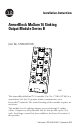
Installation Instructions ArmorBlock MaXum 16 Sinking Output Module Series B (Cat. No. 1792D-0VT16E) 42047 This ArmorBlock MaXum™ I/O module (Cat. No. 1792D-0VT16E) is a stand-alone 24V dc I/O product which communicates via a DeviceNet™ network. The sealed housing of this module requires no enclosure. This module has 16 sinking outputs accessed through Y splitter cables. Outputs are self-protected 24V dc and provide up to 0.3A each.
ArmorBlock MaXum 16 Sinking Output Module Series B Package Contents Your package contains: • 1 ArmorBlock MaXum Module • Installation Instructions Please note that cable bases are ordered and shipped separately. European Communities (EC) Directive Compliance If this product has the CE mark it is approved for installation within the European Union and EEA regions. It has been designed and tested to meet the following directives.
ArmorBlock MaXum 16 Sinking Output Module Series B 3 Install Your ArmorBlock MaXum I/O Module To install the module you must: • • • • Set the node address Mount the module to the cable base Connect the output cord sets to the MaXum module Communicate with your ArmorBlock MaXum I/O module Each of these steps is discussed in the following procedures. Set the Node Address Valid node addresses are 00 to 63.
ArmorBlock MaXum 16 Sinking Output Module Series B Refer to the illustration of the node address below. NODE ADDRESS (00-63 PGM) 9 0 1 8 7 6 5 4 2 3 MSD 9 0 1 8 7 6 5 4 2 3 LSD Bottom View of Module Example: Node Address is set at 62 (see small black dots). 30703 The module is equipped with AutoBaud detect. AutoBaud lets the module read the settings already in use on your DeviceNet network and automatically adjusts to follow those settings.
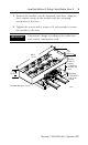
ArmorBlock MaXum 16 Sinking Output Module Series B 5 1. Position the module over the mounted cable base. Align the three captive screws in the module with the accepting receptacles in the base. 2. Tighten the screws with a torque of 8 inch-pounds to secure the module to the base. IMPORTANT Dimensions change according to the cable base and module combination used. 6.85 in 174 mm 2.7 in 68.6 mm Align the screws to properly assemble the module to the base. 1.9 in 48.
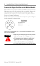
ArmorBlock MaXum 16 Sinking Output Module Series B Connect the Output Cord Sets to the MaXum Module This module uses 5 pin micro (12mm) style PCB mounted connectors. Eight micro caps cover the connectors on your module. Remove the caps and connect your cord sets to the appropriate ports. This product has two outputs per connector. Use a “Y” splitter cable for access to all output connections. Use the micro caps to cover and seal unused ports. A pinout diagram for the connectors is shown below.
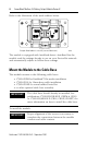
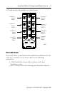
ArmorBlock MaXum 16 Sinking Output Module Series B 7 I/O connectors for this module are shown below. Connector A Output 0 Output 1 Connector B Connector H Output 15 Output 14 Output 2 Output 3 Connector G Output 13 Output 12 Connector C Output 4 Output 5 Connector F Output 11 Output 10 Connector D Output 6 Output 7 Connector E Output 9 Output 8 42048 DeviceNet Cable DeviceNet cables are described in the installation publications for the cable base assembly of your choice.
ArmorBlock MaXum 16 Sinking Output Module Series B Communicate with Your ArmorBlock MaXum I/O Module This ArmorBlock module’s I/O is exchanged with the master through a poll, change-of-state, or cyclic connection. The module consumes and produces output data as follows: Type of I/O Connections Consumes Cyclic 2 Bytes Produces 1 Byte Polled 2 Bytes 1 Byte Change-of-State 2 Bytes 1 Byte Cyclic - allows configuration of the block as an I/O client.
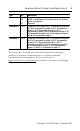
ArmorBlock MaXum 16 Sinking Output Module Series B Byte Bit Description Produces 0 00-05 06 Reserved OPWR = Output Power Fault, when the bit is set, Auxiliary Power is not present. Reserved Consumes 0 00-07 Output bits: When the bit is set (1), the output will be turned on.
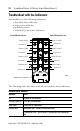
ArmorBlock MaXum 16 Sinking Output Module Series B Troubleshoot with the Indicators This module has the following indicators: • • • • Net/Mod status indicator Logic status indicator Auxiliary power Individual point status indicators Point LED Indicators for Point LED Indicators for Outputs 14 and 15 Outputs 0 and 1 Connector H Connector A Outputs 2 and 3 Outputs 12 and 13 Connector G Connector B Outputs 4 and 5 Outputs 10 and 11 Connector F Connector C Outputs 6 and 7 Outputs 8 and 9 Connect
ArmorBlock MaXum 16 Sinking Output Module Series B 11 Net/Mod Status Indicator (continued) Indicator Status Solid Red Unrecoverable fault Communication failure - duplicate node address present or incorrect baud rate Green to Red to Off At powerup only - LED test The following table describes logic status indicators.
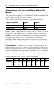
ArmorBlock MaXum 16 Sinking Output Module Series B Specifications 16 Output Module - Cat. No. 1792D-OVT16E Max. Min. Outputs per block 16 sinking outputs labeled 00 through 15 Output Auxiliary Voltage 30V 10V On-state Voltage Drop 1V - On-state Current 0.3A - Off-state Leakage 1.5mA - Module Current (all outputs) 4.0A - Surge Current - for 10 ms, repeatable every 2s 0.
ArmorBlock MaXum 16 Sinking Output Module Series B 13 16 Output Module - Cat. No.
ArmorBlock MaXum 16 Sinking Output Module Series B Hazardous Location Approval The following information applies only to products marked with Hazardous Location Approval, when operating in hazardous locations: Products marked “CL I, DIV 2, GP A, B, C, D” are suitable for use in Class I Division 2 Groups A, B, C, D, Hazardous Locations and nonhazardous locations only. Each product is supplied with markings on the rating nameplate indicating the hazardous location temperature code.
ArmorBlock MaXum 16 Sinking Output Module Series B WARNING ! 15 When used in a Class I, Division 2, hazardous location, this equipment must be mounted in a suitable enclosure with proper wiring method that complies with the governing electrical codes.
AVERTISSEMENT ! AVERTISSEMENT ! Utiliser des fils d’alimentation qui conviennent à une température de 30°C au-dessus de la température ambiante. Pour une utilisation en environnement de classe i, division 2 dangereux, cet equipement doit etre monte dans un boitier avec un cablage approprie conforme aux normes electriques en vigueur. This product has been tested at an Open DeviceNet Vendor Association, Inc. (ODVA) authorized independent test laboratory and found to comply with ODVA Conformance Test.