Installation Instructions ArmorBlock MaXum 8 Output Module Series B (Cat. No. 1792D-0B8D) 42335 This ArmorBlock MaXum™ I/O module (Cat. No. 1792D-0B8D) is a stand-alone 24V dc I/O product which communicates via a DeviceNet™ network. The sealed housing of this module requires no enclosure. This module has 8 outputs. Outputs are self-protected 24V dc and provide up to 1A each. Diagnostic features included are short circuit and no load detection reported to the point level.
ArmorBlock MaXum 8 Output Module Series B Check Package Contents Your package contains: • 1 ArmorBlock MaXum Module • Installation Instructions IMPORTANT Cable bases are ordered and shipped separately. European Communities (EC) Directive Compliance If this product has the CE mark it is approved for installation within the European Union and EEA regions. It has been designed and tested to meet the following directives.
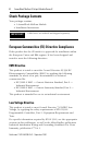
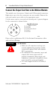
ArmorBlock MaXum 8 Output Module Series B 3 Install Your ArmorBlock MaXum I/O Module To install the module you must: • • • • Set the node address Mount the module to the cable base Connect the output cord sets to the MaXum module Communicate with your ArmorBlock MaXum I/O module More detailed information about each of these steps is in the following procedures. Set the Node Address Valid node addresses are 00 to 63.
ArmorBlock MaXum 8 Output Module Series B Refer to the illustration of the node address below. 41462 The module is equipped with AutoBaud detect. AutoBaud lets the module read the settings already in use on your DeviceNet network and automatically adjusts to follow those settings.
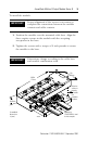
ArmorBlock MaXum 8 Output Module Series B 5 To install the module: IMPORTANT Proper alignment of the screws is necessary to complete the connections between the module contacts and cable contacts. 1. Position the module over the mounted cable base. Align the three captive screws in the module with the accepting receptacles in the base. 2. Tighten the screws with a torque of 8 inch-pounds to secure the module to the base.
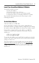
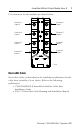
ArmorBlock MaXum 8 Output Module Series B Connect the Output Cord Sets to the MaXum Module This module uses 5 pin micro (12mm) style PCB mounted connectors. Eight micro caps cover the connectors on your module. Remove the caps and connect your cables to the appropriate ports. Use the micro caps to cover and seal unused ports. A pinout diagram for the connectors is shown below.
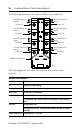
ArmorBlock MaXum 8 Output Module Series B 7 I/O connectors for this module are shown below. Connector A Output 0 Connector B Output 1 Connector C Output 2 O-0 O-7 Connector H Output 7 O-1 O-6 Connector G Output 6 O-2 O-5 O-3 O-4 Connector D Output 3 Connector F Output 5 Connector E Output 4 Auxiliary Power Logic Status Net/Mod Status 42337 DeviceNet Cable DeviceNet cables are described in the installation publications for the cable base assembly of your choice.
ArmorBlock MaXum 8 Output Module Series B Communicate with Your ArmorBlock MaXum I/O Module This ArmorBlock module’s I/O is exchanged with the master through a poll, change-of-state, or cyclic connection. The module consumes and produces output data as follows: Type of I/O Connections Consumes Cyclic 1 Bytes Produces 2 Bytes Polled 1 Bytes 2 Bytes Change-of-State 1 Bytes 2 Bytes Cyclic - allows configuration of the block as an I/O client.
ArmorBlock MaXum 8 Output Module Series B Byte Bit Description Produces 0 00-07 Output no load or overload fault (OFLT): When the bit is set (1), an output fault has occurred. OFTO corresponds to output 0, OFT1 corresponds to output 1, OFT2 corresponds to output 2, OFT3 corresponds to output 3, OFT4 corresponds to output 4, OFT5 corresponds to output 5, OFT6 corresponds to output 6, and OFT7 corresponds to output 7.
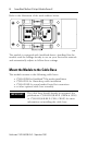
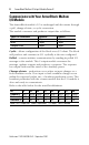
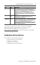
ArmorBlock MaXum 8 Output Module Series B The following illustration describes module status indicators.
ArmorBlock MaXum 8 Output Module Series B 11 The following table describes logic status indicators. Logic Status Indicators State Status Off Logic is disabled Solid Green Logic is enabled Flashing Green Local forces are applied and local logic is enabled The following table describes auxiliary status indicators. Auxiliary Status Indicators Indication Status None No Auxiliary power Solid Green Auxiliary power present The following table describes I/O status indicators.
ArmorBlock MaXum 8 Output Module Series B Specifications 8 Output Module - Cat. No. 1792D-0B8D Output Specifications Max. Min. Outputs per block 8 sourcing outputs labeled O0 through O7 Output Auxiliary Voltage 30V 10V On-state Voltage Drop 1V - On-state Current 1A - Off-state Leakage 1.5mA - Module Current (all outputs) 4.0A - Surge Current - for 10 ms, repeatable every 2s 2.4A - No Load Sense Current (On-state) 0.
ArmorBlock MaXum 8 Output Module Series B 13 8 Output Module - Cat. No. 1792D-0B8D Environmental Conditions Operational Temperature Storage Temperature Relative Humidity Shock Operating Non-operating Vibration -25 to 60oC (-13 to 140oF) -25 to 80oC (-13 to 176oF) Up to 100% 30g peak acceleration, 11 (+1) ms pulse width 50g peak acceleration, 11 (+1) ms pulse width Tested 10g @ 10-500 Hz per IEC 68-2-6 Conductors Publication DN-6.7.
ArmorBlock MaXum 8 Output Module Series B Hazardous Location Approval The following information applies only to products marked with Hazardous Location Approval, when operating in hazardous locations: Products marked “CL I, DIV 2, GP A, B, C, D” are suitable for use in Class I Division 2 Groups A, B, C, D, Hazardous Locations and nonhazardous locations only. Each product is supplied with markings on the rating nameplate indicating the hazardous location temperature code.
ArmorBlock MaXum 8 Output Module Series B WARNING ! 15 When used in a Class I, Division 2, hazardous location, this equipment must be mounted in a suitable enclosure with proper wiring method that complies with the governing electrical codes.
AVERTISSEMENT ! AVERTISSEMENT ! Utiliser des fils d’alimentation qui conviennent à une température de 30°C au-dessus de la température ambiante. Pour une utilisation en environnement de classe i, division 2 dangereux, cet equipement doit etre monte dans un boitier avec un cablage approprie conforme aux normes electriques en vigueur. This product has been tested at an Open DeviceNet Vendor Association, Inc. (ODVA) authorized independent test laboratory and found to comply with ODVA Conformance Test.