
User Manual

ArmorBlock MaXum Robot I/O Cable Base and Kempf Box Plate 11
Publication
1792D-IN054B-EN-P - April 2003
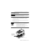
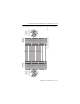
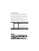
Use the graphics below to connect DeviceNet cable to your module.
1
2
4
5
6
7
8
12
14
16
17
1
2
8
7
6
5
4
12
14
16
17
Incoming
Hybrid Cable
Assembly side
Outgoing
Hybrid Cable
Assembly side
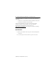
DO
~DO
DI
~DI
COM
reserved
+24V (US1)
RET (US1)
+24V (US2)
RET (US2)
CCR1
CCR2
DeviceNet High
DeviceNet Low
PE
RBST
UL
Flange
7
8
9
10
11
6
4
1
3
2
12
17
13
14
5
15
16
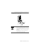
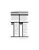
DO
~DO
SCM1 (DI)
SCM2 (~DI)
reserved (Profi B)
+24V (US1)
RET (US1)
+24V (US2)
RET (US2)
CCR1
CCR2
DeviceNet High
DeviceNet Low
PE
reserved
reserved
Flange
7
8
9
10
11
1
3
2
12
17
13
14
5
15
16
COM (Profi A)
6
4
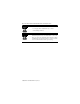
Green/Yellow
Blue
White
Red
Blue
Blue
Brown
Black
Red
Green
Red
Pink
Gray
Green
Yellow
43478
CCR = Constant current regulation
SCM = Secondary circuit monitoring
Outgoing
installation
remote bus
(Male connector)
Incoming
installation
remote bus
(Female connector)