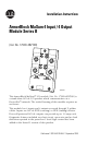
Installation Instructions ArmorBlock MaXum 4 Input / 4 Output Module Series B (Cat. No. 1792D-4BVT4D) 30702-M This ArmorBlock MaXum™ I/O module (Cat. No. 1792D-4BVT4D) is a stand-alone 24V dc I/O product which communicates via a DeviceNet™ network. The sealed housing of this module requires no enclosure. This module has 4 inputs and 4 outputs accessed through Y splitter cables. Inputs are 24V dc PNP (sourcing) or NPN (sinking) devices. Four self-protected 24V dc outputs can provide up to 1.0 amp each.
ArmorBlock MaXum 4 Input / 4 Output Module Series B Package Contents Your package contains: • 1 ArmorBlock MaXum Module • Installation Instructions (Please note: Cable bases are ordered and shipped separately.) European Union Directive Compliance If this product has the CE mark it is approved for installation within the European Union and EEA regions. It has been designed and tested to meet the following directives.
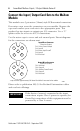
ArmorBlock MaXum 4 Input / 4 Output Module Series B 3 Install Your ArmorBlock MaXum I/O Module To install the module: • • • • Set the node address Mount the module to the cable base Connect the cord sets Communicate with the module Set the Node Address Valid node addresses are 00 to 63. Set the node address using the rotary switches, RSNetWorx for DeviceNet™, DeviceNetManager™, or other software configuration tool. Setting the switches between 64 to 99 lets the software have address control.
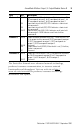
ArmorBlock MaXum 4 Input / 4 Output Module Series B See the illustration of the node address setting below. Example: Node Address is set at 62, see small black dots. 30703-M The module is equipped with AutoBaud detect. AutoBaud lets the module read the settings already in use on your DeviceNet network and automatically adjusts to follow those settings.
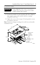
ArmorBlock MaXum 4 Input / 4 Output Module Series B 5 To install the module: IMPORTANT Proper alignment of the screws is necessary to complete the connections between the module contacts and the cable contacts. 1. Position the module over the mounted cable base. Align the three captive screws in the module with the accepting receptacles in the base. 2. Tighten the screws with a torque of 8 inch-pounds to secure the module to the base.
ArmorBlock MaXum 4 Input / 4 Output Module Series B Connect the Input / Output Cord Sets to the MaXum Module This module uses 5 pin micro (12mm) style PCB mounted connectors. Four micro caps cover the connectors on your module. Remove the caps and connect your cord sets to the appropriate ports. This product has two inputs or outputs per I/O connector. Use a “Y” splitter cable for access to all I/O connections. Use the micro caps to cover and seal unused ports.
ArmorBlock MaXum 4 Input / 4 Output Module Series B ATTENTION ! 7 • Make sure all connectors and caps are securely tightened to properly seal the connections against leaks and maintain IP67 requirements. • For maximum noise immunity, input and output cable return wires must be properly terminated. When inputs and outputs are connected in loopback, return wires should be connected together. • I/O cable length should be less than 30 meters. I/O connectors for this module are shown below.
ArmorBlock MaXum 4 Input / 4 Output Module Series B Communicate With Your ArmorBlock MaXum I/O Module This ArmorBlock module’s I/O is exchanged with the master through a polled, change-of-state, or cyclic connection. The module consumes and produces I/O data as follows: Type of I/O Connections Consumes Produces Cyclic 1 Byte 2 Bytes Polled 1 Byte 2 Bytes Change-of-State 1 Byte 2 Bytes Cyclic - allows configuration of the block as an I/O client.
ArmorBlock MaXum 4 Input / 4 Output Module Series B Byte Bit Description Produces 0 00-03 Input status bits: When the bit is set (1), the input is on. Bit 00 corresponds to input 0, bit 01 corresponds to input 1, bit 02 corresponds to input 2, bit 03 corresponds to input 3. Input short circuit fault (ISC): ISC-A indicates a short circuit for connector A. Input short circuit fault (ISC): ISC-B indicates a short circuit for connector B.
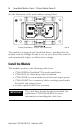
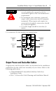
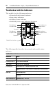
ArmorBlock MaXum 4 Input / 4 Output Module Series B Troubleshoot with the Indicators This module has the following indicators: • • • • Network/Module status indicator Logic status indicators Auxiliary Power indicator Individual point status indicators for inputs Point indicators for inputs 0 and 1 I0 O0 I1 O1 Point indicators for outputs 0 and 1 Connector C Connector A Point indicators for inputs 2 and 3 I2 O2 I3 O3 Point indicators for outputs 2 and 3 Connector D Connector B Auxiliary Pow
ArmorBlock MaXum 4 Input / 4 Output Module Series B 11 The following table describes logic status indicators. Logic Status Indicators State Status Off Logic is disabled Solid Green Logic is enabled Flashing Green Local forces are applied and local logic is enabled The following table describes auxiliary power indicators. Auxiliary Power Indication Status None No Auxiliary Power Solid Green Auxiliary Power Present The following table describes I/O status indicators.
ArmorBlock MaXum 4 Input / 4 Output Module Series B Specifications 4 Input / 4 Output Module - Cat. No. 1792D-4BVT4D Input Specifications Max. Inputs per block 4 - 3 wire or dry contact PNP or NPN devices or 2 4 wire PNP or NPN devices Sensor Source Current (per connection) 100mA total - Off-Wire Sense Current 0.5mA - On-state Voltage 25V dc 10V dc On-state Current 10mA 2mA Off-state Voltage 5V dc - Off-state Current - 1.5mA Output Specifications Max. Outputs per block Min.
ArmorBlock MaXum 4 Input / 4 Output Module Series B 13 4 Input / 4 Output Module - Cat. No. 1792D-4BVT4D General Specifications (cont.) Dimensions (assembled to base) inches - (Millimeters) Environmental Conditions Operational Temperature Storage Temperature Relative Humidity Shock Operating Non-operating Vibration 1.9H x 2.7w x 4.72D (48.26)H x (68.
ArmorBlock MaXum 4 Input / 4 Output Module Series B Hazardous Location Approval The following information applies only to products marked with Hazardous Location Approval, when operating in hazardous locations: Products marked “CL I, DIV 2, GP A, B, C, D” are suitable for use in Class I Division 2 Groups A, B, C, D, Hazardous Locations and nonhazardous locations only. Each product is supplied with markings on the rating nameplate indicating the hazardous location temperature code.
ArmorBlock MaXum 4 Input / 4 Output Module Series B WARNING ! 15 When used in a Class I, Division 2, hazardous location, this equipment must be mounted in a suitable enclosure with proper wiring method that complies with the governing electrical codes.
AVERTISSEMENT ! AVERTISSEMENT ! Utiliser des fils d’alimentation qui conviennent à une température de 30°C au-dessus de la température ambiante. Pour une utilisation en environnement de classe i, division 2 dangereux, cet equipement doit etre monte dans un boitier avec un cablage approprie conforme aux normes electriques en vigueur. 7his product has been tested at an Open DeviceNet Vendor Association, Inc. (ODVA) authorized independent test laboratory and found to comply with ODVA Conformance Test.