Installation Instructions ArmorBlock MaXum 4 Input Module Series B (Cat. No. 1792D-4BV0D) 41455 This ArmorBlock MaXum I/O module (Cat. No. 1792D-4BV0D) is a stand-alone 24V dc I/O product which communicates via a DeviceNet network. The sealed housing of this module requires no enclosure. This model has 4 inputs. Inputs are 24V dc automatically configured for PNP (sourcing) or NPN (sinking) devices. Diagnostic features included are short circuit and open wire detection reported to the point level.
ArmorBlock MaXum 4 Input Module Series B Package Contents Your package contains: • 1 ArmorBlock MaXum Module • Installation Instructions (Note: Cable bases are ordered and shipped separately.) European Union Directive Compliance If this product has the CE mark it is approved for installation within the European Union and EEA regions. It has been designed and tested to meet the following directives.
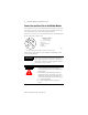
ArmorBlock MaXum 4 Input Module Series B 3 Install Your ArmorBlock MaXum I/O Module To install the module: • • • • Set the node address Mount the module to the cable base Connect the cord sets Communicate with the module These steps are explained in more detail in the following procedures. Set the Node Address Valid node addresses are 00 to 63. Set the node address using the rotary switches, RSNetWorx for DeviceNet, DeviceNetManager, or other software configuration tool.
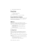
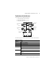
ArmorBlock MaXum 4 Input Module Series B See the illustration of the node address below. NODE ADDRESS (00-63 PGM) 9 0 1 8 7 6 5 4 2 3 MSD 9 0 1 8 7 6 5 4 2 3 LSD Bottom View of Module Example: Node Address is set at 62, see small black dots.
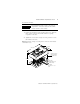
ArmorBlock MaXum 4 Input Module Series B 5 To install the module: IMPORTANT Proper alignment of the screws is necessary to complete the connections between the module contacts and the cable contacts. 1. Position the module over the mounted cable base. Align the three captive screws in the module with the accepting receptacles in the base. 2. Tighten the screws with a torque of 8 inch-pounds to secure the module to the base. Note: Dimensions change according to the cable base and module combination used.
ArmorBlock MaXum 4 Input Module Series B Connect the Input Cord Sets to the MaXum Module This module uses 5 pin micro (12mm) style PCB mounted connectors. Four micro caps cover the connectors on your module. Remove the caps and connect your cables to the appropriate ports. Use the micro caps to cover and seal unused ports. A Pinout diagram for the connector is shown next.
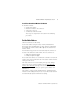
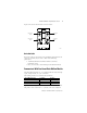
ArmorBlock MaXum 4 Input Module Series B 7 Input connectors for this module are shown below. Connector A Input 0 Connector D Input 3 Connector B Input 1 Connector C Input 2 41461 DeviceNet Cable DeviceNet cables are described in the installation publications for the cable base assembly of your choice. Refer to the following publications: • 1792D-IN009B-EN-P ArmorBlock MaXum Cable Base Installation Guide • DN-6.7.
ArmorBlock MaXum 4 Input Module Series B Polled - a master initiates communication by sending its polled I/O message to the module. The 4 input module scans the inputs and fault bits producing a response that reflects their status. Change-of-state - productions occur when an input changes or a fault condition occurs. If no input or fault condition change occurs within the expected packet rate, a heartbeat production occurs.
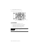
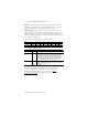
ArmorBlock MaXum 4 Input Module Series B 9 Troubleshoot with the Indicators This module has the following indicators: • Network/Module status indicator • Logic status indicator • Individual point status indicators Point indicator for input 3 Point indicator for input 0 Connector A Connector D Point indicator for input 1 Point indicator for input 2 Connector B Connector C Module Status Indicators 41461 LED Assignments The following table describes network and module status indicators.
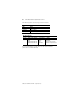
ArmorBlock MaXum 4 Input Module Series B The following table describes logic status indicators. Logic Status Indicators State Status Off Logic is disabled Solid Green Logic is enabled Flashing Green Local forces are applied and local logic is enabled The following table describes I/O status indicators.
ArmorBlock MaXum 4 Input Module Series B 11 Specifications 4 Input Module - Cat. No. 1792D-4BV0D Input Specifications Max. Inputs per block 4 - 3 wire or dry contact PNP or NPN devices Min. Sensor Source Current (per input) 100mA - Off-Wire Sense Current 0.
ArmorBlock MaXum 4 Input Module Series B Hazardous Location Approval The following information applies only to products marked with Hazardous Location Approval, when operating in hazardous locations: Products marked “CL I, DIV 2, GP A, B, C, D” are suitable for use in Class I Division 2 Groups A, B, C, D, Hazardous Locations and nonhazardous locations only. Each product is supplied with markings on the rating nameplate indicating the hazardous location temperature code.
ArmorBlock MaXum 4 Input Module Series B WARNING ! 13 When used in a Class I, Division 2, hazardous location, this equipment must be mounted in a suitable enclosure with proper wiring method that complies with the governing electrical codes.
ArmorBlock MaXum 4 Input Module Series B AVERTISSEMENT ! AVERTISSEMENT ! Utiliser des fils d’alimentation qui conviennent à une température de 30°C au-dessus de la température ambiante. Pour une utilisation en environnement de classe i, division 2 dangereux, cet equipement doit etre monte dans un boitier avec un cablage approprie conforme aux normes electriques en vigueur. This product has been tested at an Open DeviceNet Vendor Association, Inc.
ArmorBlock MaXum 4 Input Module Series B 15 Notes: Publication 1792D-IN017B-EN-P - September 2000
ArmorBlock, ArmorBlock MaXum and KwikLink are trademarks of Rockwell Automation. RSNetWorx for DeviceNet is a trademark of Rockwell Software, Inc. DeviceNetManager is a trademark of Rockwell Automation Allen-Bradley. Inc. DeviceNet is a trademark of Open DeviceNet Vendor Association (ODVA). Publication 1792D-IN017B-EN-P - September 2000 Supersedes Publication 1792D-5.17 - October 1998 PN 957395-42 © 2000 Rockwell International Corporation.