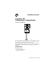
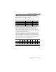
Installation Instructions ArmorBlock LP2 4 Sinking Input / 4 Output Module (Cat. No. 1792D-4BT4LP) I0 O0 I1 O1 I2 O2 I3 O3 Auxiliary Power Network Status Module Status 41622 This ArmorBlock LP2 I/O module (Cat. No. 1792D-4BT4LP) is a standalone 24V dc I/O product which communicates via a DeviceNet network. The sealed housing of this module requires no enclosure. This module has 4 sinking inputs and 4 sourcing outputs accessed through Y splitter cables.
4 Sinking Input / 4 Output Module European Union Directive Compliance If this product has the CE mark it is approved for installation within the European Union and EEA regions. It has been designed and tested to meet the following directives.
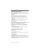
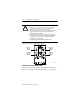
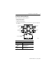
4 Sinking Input / 4 Output Module 3 Install the Module 1. Attach the module using the dimensions shown below. 1.95 in 49.5mm 12in 305mm I0 I3 I1 I2 Network Status 4.21 in 107mm Module Status 0.25 in 6.25mm 1.02 in 26.0mm 2. Connect the grey DeviceNet cable to the DeviceNet trunk. Use the 1485P-P1R5-MN5R1 T-Part tap to connect to round media. Use the 1485P-P1E4-R5 to connect to the Kwik Link flat media system.
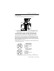
4 Sinking Input / 4 Output Module ATTENTION: ! • Make sure to connect the proper color coded cables together. DeviceNet cable should connect to DeviceNet cables and auxillary outputs should match auxillary outputs. • Make sure all connectors and caps are securely tightened to properly seal the connections against leaks and maintain IP67 requirements • For maximum noise immunity, input and output cable return wires must be properly terminated.
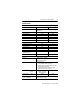
4 Sinking Input / 4 Output Module 5 Communicate With Your ArmorBlock LP2 I/O Module This ArmorBlock module’s I/O is exchanged with the master through a polled, change of state, or cyclic connection. The module consumes and produces I/O data as follows: Type of I/O Connections Consumes Produces Cyclic 1 Byte 1 Byte Polled 1 Byte 1 Byte Change of State 1 Byte 1 Byte Cyclic - allows configuration of the block as an I/O client.
4 Sinking Input / 4 Output Module Byte Produces 0 Bit Description 00-03 04 Input status bits: When the bit is set (1), the input is on. Bit 00 corresponds to input 0, bit 01 corresponds to input 1, bit 02 corresponds to input 2, bit 03 corresponds to input 3. Reserved 05 Reserved 06 Output Powr Fault (OPWR): When the bit is set (1) auxilary power is not present. Reserved 07 00-03 Consumes 0 04-07 Output bits: When the bit is set (1), the output will be turned on.
4 Sinking Input / 4 Output Module 7 Troubleshoot with the Indicators This module has the following indicators: • • • • Network status indicator Module status indicator Auxiliary Power indicator Individual point status indicators for inputs 0, 1, 2, and 3 and outputs 0, 1, 2, and 3.
4 Sinking Input / 4 Output Module Network Status Indicator Indication Status None Not On-line Green Blinking Solid On-line/No Connections On-line/Connected Red Blink Solid Connection Timed Out Failed Communication: A duplicate node address exists or module is at the wrong baud rate.
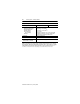
4 Sinking Input / 4 Output Module 9 Specifications 4 Input / 4 Output Module - Cat. No. 1792D-4BT4LP Sinking Input Specifications Max Inputs per block 4 - 3 wire or dry contact PNP devices or 2 - 4 wire PNP devices Min Sensor Source Current (per input) 50mA - On-state Voltage 25V dc 10V dc On-state Current 10mA 2mA Off-state Voltage 5V dc Off-state Current 1.
4 Sinking Input / 4 Output Module 4 Input / 4 Output Module - Cat. No. 1792D-4BT4LP General Specifications Cont. Environmental Conditions Operational Temperature Storage Temperature Relative Humidity Shock Operating Non-operating Vibration Conductors Max Min -25 to 60o (-13 to 140oF) -25 to 80oC (-13 to 176OF) Up to 100% 30g peak acceleration, 11 (+1) ms pulse width 50g peak acceleration, 11(+1)ms pulse width Tested 10g @ 10-500Hz per IEC 68-2-6 Publication DN-6.7.
4 Sinking Input / 4 Output Module 11 Publication 1792D-5.
4 Sinking Input / 4 Output Module Publication 1792D-5.26 - January 1999 PN 955134-80 1999 Rockwell International. All Rights Reserved.