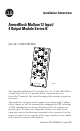
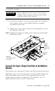
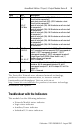
Installation Instructions ArmorBlock MaXum 12 Input/ 4 Output Module Series B (Cat. No. 1792D-12BVT4D) O-0 O-3 O-1 O-2 I-0 I-11 I-1 I-10 I-2 I-3 I-9 I-8 I-4 I-7 I-5 I-6 Auxilary Power Logic Status Net/Mod Status 42338 This ArmorBlock MaXum™ I/O module (Cat. No. 1792D-12BVT4D) is a stand-alone 24V dc I/O product which communicates via a DeviceNet™ network. The sealed housing of this module requires no enclosure. This model has 12 inputs and 4 outputs accessed through Y splitter cables.
ArmorBlock MaXum 12 Input/ 4 Output Module Series B Check Package Contents Your package contains: • 1 ArmorBlock MaXum Module • Installation Instructions (Please note: Cable bases are ordered and shipped separately.) European Union Directive Compliance If this product has the CE mark it is approved for installation within the European Union and EEA regions. It has been designed and tested to meet the following directives.
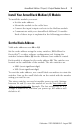
ArmorBlock MaXum 12 Input/ 4 Output Module Series B 3 Install Your ArmorBlock MaXum I/O Module To install the module you must: • • • • Set the node address Mount the module to the cable base Connect the input/output cord sets to the MaXum module Communicate with your ArmorBlock MaXum I/O module Each of these steps is explained in the following procedures. Set the Node Address Valid node addresses are 00 to 63.
ArmorBlock MaXum 12 Input/ 4 Output Module Series B Refer to the illustration of the node address below. 41462 The module is equipped with AutoBaud detect. AutoBaud lets the module read the settings already in use on your DeviceNet network and automatically adjusts to follow those settings.
ArmorBlock MaXum 12 Input/ 4 Output Module Series B 5 To install the module: IMPORTANT Proper alignment of the screws is necessary to complete the connections between the module contacts and the cable contacts. 1. Position the module over the mounted cable base. Align the three captive screws in the module with the accepting receptacles in the base. 2. Tighten the screws with a torque of 8 inch-pounds to secure the module to the base.
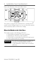
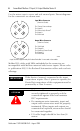
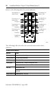
ArmorBlock MaXum 12 Input/ 4 Output Module Series B Use the micro caps to cover and seal unused ports. Pinout diagrams for the connectors are shown next. Input Micro-Connector (View into Socket) Pin 1 Sensor Source voltage Pin 2 Input B Pin 3 Return Logic Ground1 Pin 4 Input A Pin 5 Not Used Output Micro-Connector (View into Socket) Pin 1 Not Used Pin 2 Output B Pin 3 Auxiliary Power Ground Pin 4 Output A Pin 5 Not Used 41452 1Logic Ground is approximately 0.
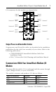
ArmorBlock MaXum 12 Input/ 4 Output Module Series B 7 I/O connectors for this module are shown below.
ArmorBlock MaXum 12 Input/ 4 Output Module Series B Cyclic - allows configuration of the block as an I/O client. The block will produce and consume its I/O cyclically at the rate configured. Polled device - a master initiates communication by sending its polled I/O message to the module. The 12 input / 4 output module consumes the message, updates outputs, and produces a response. The response has input data, input faults, output faults, and the status of the Auxiliary power.
ArmorBlock MaXum 12 Input/ 4 Output Module Series B Byte Bit Description Produces 2 00-01 ISC Input short circuit fault (ISC): (ISC-E indicates a short circuit fault for connector E. Input short circuit fault ((ISC): (ISC-F indicates a short circuit fault for connector F. Input off wire fault (OW): OW-A indicates an off-wire fault for connector A. Input off wire fault (OW): OW-B indicates an off-wire fault for connector B. Input off wire fault (OW): OW-C indicates an off-wire fault for connector C.
ArmorBlock MaXum 12 Input/ 4 Output Module Series B Refer to the following table for point indicators.
ArmorBlock MaXum 12 Input/ 4 Output Module Series B 11 The following table describes logic status indicators. Logic Status Indicators State Status Off Logic is disabled Solid Green Logic is enabled Flashing Green Local forces are applied and local logic is enabled The following table describes auxiliary status indicators. Auxiliary Status Indicators Indication Status None No Auxiliary power Solid Green Auxiliary power present The following table describes I/O status indicators.
ArmorBlock MaXum 12 Input/ 4 Output Module Series B Specifications 12 Input / 4 Output Module - Cat. No. 1792D-12BVT4D Input Specifications Max. Inputs per block 12 - 3 wire or dry contact PNP or NPN devices or 6 4 wire PNP or NPN devices Min. Sensor Source Current (per input) See the graph below. Off-Wire Sense Current 0.5mA - On-state Voltage 25V dc 10V dc On-state Current 10mA 2mA Off-state Voltage 5V dc - Off-state Current - 1.5mA Output Specifications Max.
ArmorBlock MaXum 12 Input/ 4 Output Module Series B 13 12 Input / 4 Output Module - Cat. No. 1792D-12BVT4D General Specifications (continued) Environmental Conditions Operational Temperature Storage Temperature Relative Humidity Shock Operating Non-operating Vibration -25 to 60° (-13 to 140°F) -25 to 80° (-13 to 176°F) 5 to 100% 30g peak acceleration, 11 (+1) ms pulse width 50g peak acceleration, 11 (+1) ms pulse width Tested 10g @ 10-500Hz per IEC 86-2-6 Conductors Publication DN-6.7.
ArmorBlock MaXum 12 Input/ 4 Output Module Series B Hazardous Location Approval The following information applies only to products marked with Hazardous Location Approval, when operating in hazardous locations: Products marked “CL I, DIV 2, GP A, B, C, D” are suitable for use in Class I Division 2 Groups A, B, C, D, Hazardous Locations and nonhazardous locations only. Each product is supplied with markings on the rating nameplate indicating the hazardous location temperature code.
ArmorBlock MaXum 12 Input/ 4 Output Module Series B WARNING ! 15 When used in a Class I, Division 2, hazardous location, this equipment must be mounted in a suitable enclosure with proper wiring method that complies with the governing electrical codes.
AVERTISSEMENT ! AVERTISSEMENT ! Utiliser des fils d’alimentation qui conviennent à une température de 30°C au-dessus de la température ambiante. Pour une utilisation en environnement de classe i, division 2 dangereux, cet equipement doit etre monte dans un boitier avec un cablage approprie conforme aux normes electriques en vigueur. This product has been tested at an Open DeviceNet Vendor Association, Inc. (ODVA) authorized independent test laboratory and found to comply with ODVA Conformance Test.