
Owner's manual
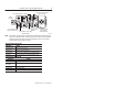

ArmorBlock-LP 8 Input/8 Output Module6
Publication
1792-5.8 – December 1997
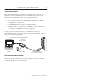
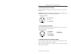
Connecting the Output Power Wiring
Connect output power wiring to the 3-pin mini-connector on the end of
the block.
Important:
The outputs use electronic overcurrent fault protection. Make certain
your output power supply can handle overcurrent events.
1
2
3
Ou
t
pu
t P
o
w
er
Mini-
Co
nn
e
ct
or
Pin 1 = Chassis ground
Pin 2 = +24V dc
Pin 3 = Negative/Return
(View into pins)
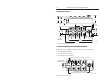
Connecting the DeviceNet Wiring
Connect DeviceNet wiring to the 5-pin mini-connector on the end of the
block. Connections are shown below.
1
2
3
D
e
vic
e
N
e
t Mini-
Co
nn
e
ct
or
Pin 1 = Drain (Bare)
Pin 2 = V+ (Red)
Pin 3 = V– (Black)
(View into pins)
4
5
Pin 4 = CAN–HI (White)
Pin 5 CAN–LO (Blue)
Note: Colors are
DeviceNet standard
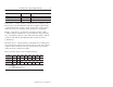
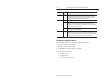
Communicate with Your ArmorBlock Module
This ArmorBlock module’s I/O is exchanged with the master through a
poll, bit strobe or change of state connection.
When set for Polled, Bit Strobe, or change of state, the module consumes
and produces as follows: