
Owner's manual

ArmorBlock-LP 8 Input/8 Output Module 5
Publication
1792-5.8 – December 1997
Seven micro caps are included with your module. Use these caps to
cover and seal unused ports. Pinout diagrams for the connectors are
shown below.
!
ATTENTION: Make sure all connectors are securely
tightened to properly seal the connections against leaks and
maintain IP67 requirements.
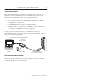
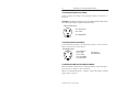
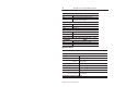
Connecting the Input Wiring
Connect input wiring to the micro-connectors which screw into mating
connectors on the front of the block.
1
2
34
I/O
I
n
pu
t Mic
ro
-
Co
nn
e
ct
or
Pin 1 = Sensor Source V
oltage Positive
Pin 2 = Signal B
Pin 3 = Negative/Return
Pin 4 = Signal A
(V
iew into socket)
5
Pin 5 = Ground
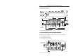
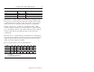
Connecting the Output Wiring
Connect output wiring to the micro-connectors which screw into mating
connectors on the front of the block.
1
2
34
I/O
Ou
t
pu
t Mic
ro
-
Co
nn
e
ct
or
Pin 1 = No connection
Pin 2 = Signal B
Pin 3 = Negative/Return
Pin 4 = Signal A
(V
iew into socket)
5
Pin 5 = Ground